PowerFlex® 700S Drives - Phase I Control (Frame Sizes 9 & 10) 39
Table O Analog Wiring Examples
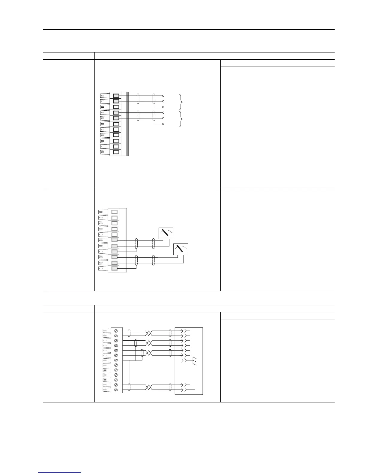
Analog I/O Connection Example
Analog Inputs
- +/-10V DC or +/-1.0V
DC (DIP switch setable)
Terminate shields at the
analog source if analog
common is available
Used for Speed
Reference and Speed
Tr i m
Analog Inputs - shield terminated at source Required Parameter Changes
Using Analog In1 as 0 - 10 V speed reference:
• Scale the Input to 1 V
Par 802 [Anlg ln1 Scale] = 0.1
• Send the data to the Speed Reference parameter
Par 10 [Speed Ref 1] (the destination) linked to Par
800 [Anlg ln1 Data] (the source)
• Select Ref 1 as the active speed ref
Par 16 [Speed Ref Sel] = 1 “Spd Ref 1”
• Par 153 [Control Options], bit 0 “Bipolar SRef” = 0
(Unipolar Speed Reference)
Using Analog In2 as -10 to +10V speed trim @ 10%:
• Scale the input to 0.1V - 10%
Par 808 [Anlg ln2 Scale] = 0.1
• Send the data to the speed reference parameter
Par 12 [Speed Ref 2] (the destination) linked to Par
806 [Anlg ln2 Data] (the source)
• Select Ref 1 as the active speed reference and Ref2
as trim
• Set Par 16 [Speed Ref Sel] = 3 “Spd Ref 3”
Analog Outputs - +/
-10V DC
Used to drive analog
meters displaying speed
and current
Using Analog Out 1, -10V to + 10V to meter Motor
RPM and direction:
• Send the data to the Analog Output
Par 815 [Anlg Out1 Real] (the destination) linked to
Par 300 [Motor Spd Fdbk] (the source)
• Scale the Output to the source parameter
Par 817 [Anlg Out1 Scale] = 175 (Par 4 [Motor NP
RPM] = 1750 / 10V)
Using Analog Out 2, -10V to + 10V to meter Motor
Current:
• Send the data to the Analog Output
Par 820 [Anlg Out2 Real] (the destination) linked to
Par 308 [Output Current] (the source)
• Scale the Output to the source parameter
Par 822 [Anlg Out2 Scale] = xx (Par 2 [Motor NP
FLA] / 10 V)
Table P Encoder Wiring Example
Input/Output Connection Example
Primary Encoder
Interface -
Supports 12V DC
differential encoders with
internal power supply.
5V DC differential
encoders require
external power supply
and special jumper
settings.
Used as primary closed
loop speed feedback
Primary Encoder - using internal power supply Required Parameter Changes
Using Encoder 0 as speed feedback:
• Par 222 [Motor Fdkbk Sel] = 0 “Encoder 0” (= default)
• Par 232 [Encoder0 PPR] = Pulses/Rev for installed
encoder
11
10
8
7
-
+
Common
(Return)
Analog Input #1
Speed
Reference
-
+
Common
(Return)
Analog Input #2
Speed
Tr im
TB1 - Row B (Bottom)
+-
+-
2
3
4
5
6
1
Output #1
Motor
Speed
Output #2
Motor
Current
TB1 - Row B (Bottom)
1312111098721
POWER
COMMON
(RETURN)
AA
BBZZ
CASE GROUND
TB2 - Row T (Top)

 Loading...


