42 PowerFlex® 700S Drives - Phase I Control (Frame Sizes 9 & 10)
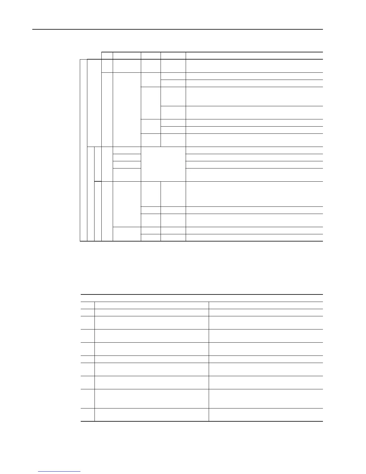
Table Q Drive Status Indicator Descriptions
6. Examine the Status (STS) LED. Verify that it is flashing green. If it is not in this
state, check the following possible causes and take the necessary corrective
action.
Table R Common Causes of a Pre-Start Alarm
# Name Color State Description
DRIVE
Power Structure
➊
PWR
(Power)
Green Steady Illuminates when power is applied to the drive.
➋
STS
(Status)
Green Flashing Drive ready, but not running & no faults are present.
Steady Drive running, no faults are present.
Yellow Flashing When running, a type 2 (non-configurable) alarm condition exists,
drive continues to run. When stopped, a start inhibit exists and the
drive cannot be started.
Steady A type 1 (user configurable) alarm condition exists, but drive
continues to run.
Red Flashing A fault has occurred.
Steady A non-resettable fault has occurred.
Red /
Ye l l o w
Flashing
Alternately
The drive is in flash recovery mode. The only operation permitted is
flash upgrade.
Control Assembly
Communications
➌
PORT Refer to the
Communication
Adapter User Manual
Status of DPI port internal communications (if present).
MOD Status of communications module (when installed).
NET A Status of network (if connected).
NET B Status of secondary network (if connected).
Control
(1)
SYNCHLINK Green Steady The module is configured as the time keeper.
or
The module is configured as a follower and synchronization is
complete.
Green Flashing The follower(s) are not synchronized with the time keeper.
Red Flashing The module is configured as a time master on SynchLink and has
received time information from another time master on SynchLink.
ENABLE Green On The drive’s enable input is high.
Green Off The drive’s enable input is low.
(1) SynchLink LEDS are located on the SynchLink daughtercard on the main circuit board in the control cassette.
Examine Parameter 156 [Run Inhibit Status]
bit Description Action
1 No power is present at the Enable Terminal TB1 - T7 Apply the enable
2, 3,
4
A stop command is being issued Close all stop inputs
5 Power loss event is in progress, indicating a loss of the
AC input voltage
Restore AC power
6 Data supplied by the power structure EEprom is invalid or
corrupt.
Cycle power. If problem persists, replace the power
structure.
7 Flash Update in Progress Complete Flash Procedures
8 Drive is expecting a Start Edge and is receiving a
continuous signal.
Open all start buttons and remove all start commands
9 Drive is expecting a Jog Edge and is receiving a
continuous signal.
Open all jog buttons and remove all jog commands
10 A conflict exists between the Encoder PPR programming
(Par 232 or 242) and the encoder configuration for edge
counts (Par 233 or 243, bits 4 & 5).
Verify encoder data and reprogram
11 The drive cannot precharge because a precharge input is
programmed and no signal is present.
Reprogram the input or close the precharge control
contact.

 Loading...


