54 Rockwell Automation Publication 750-QS001A-EN-P - March 2015
Reference Section
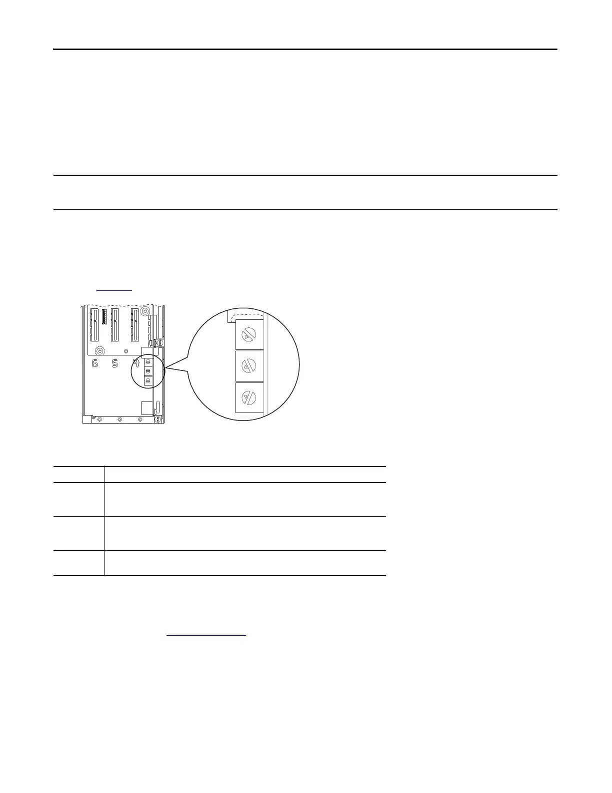
Setting the IP Address Using the Adapter Rotary Switches
You can use the rotary switches to set the IP address if the following are met.
• The IP address follows the format 192.168.1.xxx
• The subnet mask is 255.255.255.0
•There is no gateway address
1. Verify that the drive is not powered.
2. Set the IP address to a valid address (001…254) by turning the rotary switches using a small screwdriver.
For example, if the IP address needs to be 192.168.1.123, turn the top switch so the arrow is pointing at 1, turn the
middle
switch so the arrow is pointing at 2, and turn the bottom switch so the arrow is pointing at 3.
See Tab le
35 for more information on the address settings.
3. Apply power to the drive.
4. Verify communication has been established.
If communication is not established, refer to the PowerFlex 755 Drive Embedded EtherNet/IP Adapter User
Ma
nual, publication
750COM-UM001 and/or your network administrator to validate connectivity.
When using the adapter rotary switches, set the IP address before power is applied because the adapter uses the IP address it
detects when it first receives power.
Table 35 - IP Address Settings and Descriptions
Settings Description
001…254 The adapter will use the rotary switch settings for the IP addr
ess (192.168.1.xxx, where xxx = rotary
switch settings).
The value stored in parameter 36 - [BOOTP] is automatically ignored.
888 Resets the adapter IP address function to factory defaults. Thereafter, the drive must be powered
down,
the switches set to a correct value (001…254), and then the drive must be powered up again
to accept the new address.
Any other
set
ting
Disables the rotary switches and requires using parameter 36 - [BOOTP] to select the BOOTP server
as the source for the IP address or, if disabled, selects the adapter parameters as the source.
0
5
4
9
3
8
2
7
1
6
0
5
4
9
3
8
2
7
1
6
0
5
4
9
3
8
2
7
1
6

 Loading...


