2-124 Process PI Loop
– If the current limit or voltage limit is active then the PI is put into
hold.
• PI Reset – This feature holds the output of the integral function at
zero. The term “anti windup” is often applied to similar features. It
may be used for integrator preloading during transfer and can be used
to hold the integrator at zero during “manual mode”. Take the
example of a process whose feedback signal is below the reference
point, creating error. The drive will increase its output frequency in an
attempt to bring the process into control. If, however, the increase in
drive output does not zero the error, additional increases in output will
be commanded. When the drive reaches programmed Maximum
Frequency, it is possible that a significant amount of integral value
has been “built up” (windup). This may cause undesirable and sudden
operation if the system were switched to manual operation and back.
Resetting the integrator eliminates this windup.
NOTE: In the PowerFlex 70, once the drive has reached the
programmable positive and negative PI limits, the integrator stops
integrating and no further “windup” is possible.
3. [PI Status] parameter is a set of bits that indicate the status of the
process PI controller
• Enabled – The loop is active and controlling the drive output.
• Hold – A signal has been issued and the integrator is being held at its
current value.
• Reset – A signal has been issued and the integrator is being held at
zero.
• In Limit – The loop output is being clamped at the value set in [PI
Upper/Lower Limit].
PI Reference and Feedback
The selection of the source for the reference signal is entered in the PI
Reference Select parameter. The selection of the source for the feedback
signal is selected in the PI Feedback Select parameter. The reference and
feedback have the same limit of possible options.
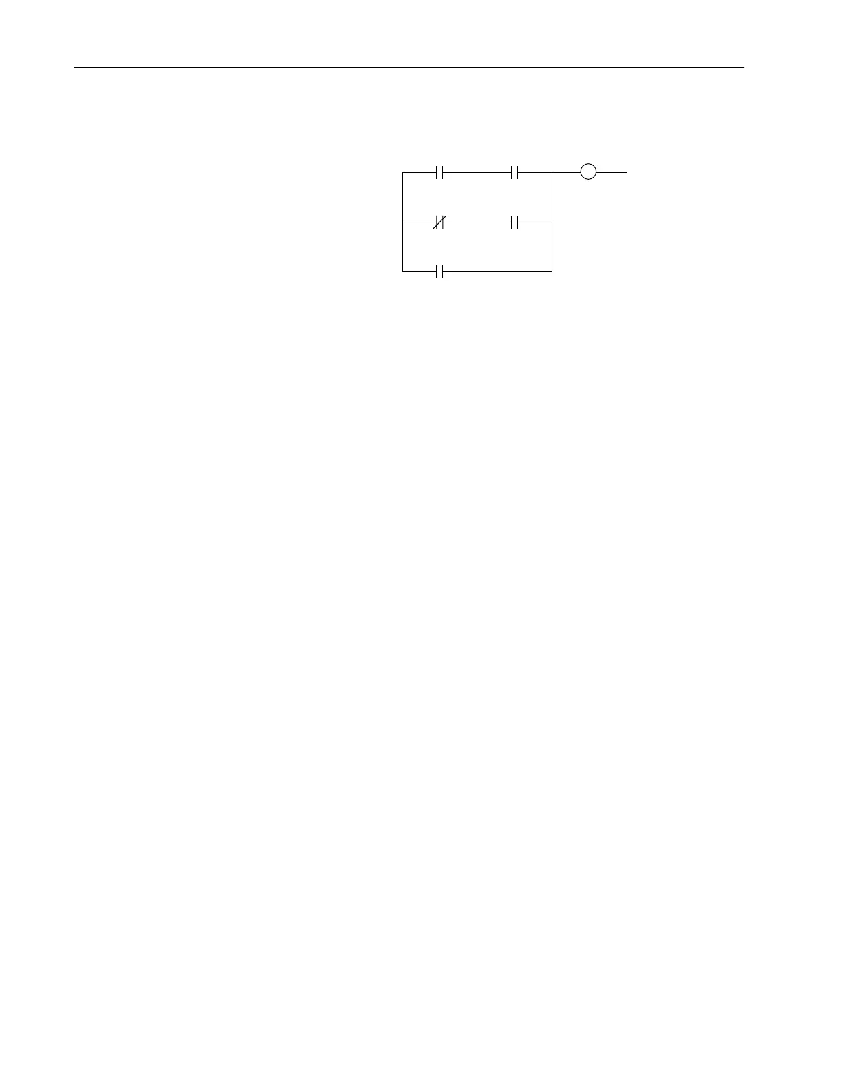
PI_Status
.Hold
DigInCfg
.PI_Hold
DigInCfg
.PI_Hold
DigIn
.PI_Hold
PI_Control
.PI_Hold
Current Lmt
or Volt Lmt

 Loading...


