2-36 Cable, Standard I/O
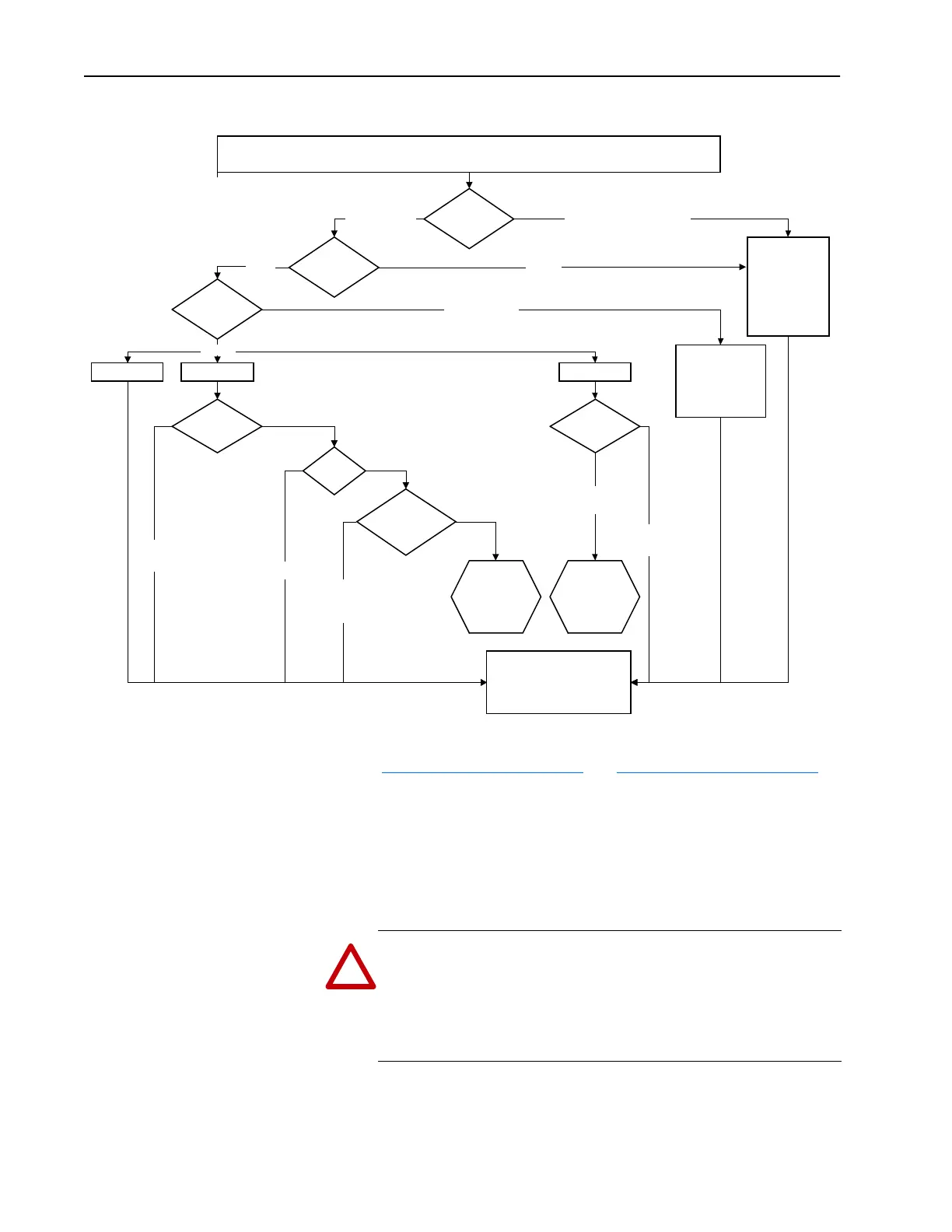
Figure 2.5 Wire Selection Flowchart
Cable, Standard I/O Refer to Cable Selection on page 2-15 and Cable Selection on page 2-46.
CabIe Trays and
Conduit
Important:Because of the nature of the drive PWM output and the
reflected wave phenomenon, it is preferable to have each set of
drive motor/power cables in an individual conduit. If this is not
possible, it is important that the allowable fill rates specified in
the applicable national or local codes NOT BE Exceeded.
Carrier (PWM)
Frequency
This section is under construction. If further information is required, please
contact factory.
Selecting Wire to Withstand Reflected Wave Voltage for New and Existing Wire Installations
in Conduit or Cable Trays
Conductor
Environment
Conductor
Insulation
Insulation
Thickness
XLPE
PVC
OK for < 600V AC
System
No RWR or
Terminator required
20 mil or > (1)
230V 400/460V
15 mil
RWR or
Terminator
No RWR or
Terminator
Cable
Length
# of
Drives in Same
Conduit or Wire
Tray
> 50 ft.
< 50 ft.
Single Drive,
Single Conduit
or Wire Tray
Multiple Drives
in Single Conduit
or Wire Tray
575V
No RWR
or Terminator
Reflected Wave
Reducer?
Reflected Wave
Reducer?
RWR or
Terminator
XLPE (XHHW-2)
Insulation for
<600V AC
System
No RWR or
Terminator
Required
15 mil PVC
Not
Recommended
USE XLPE
or > 20 mil
15 mil PVC
Not
Recommended
USE XLPE
or > 20 mil
See NEC Guidelines
(70-196 Adjustment Factors) for
Maximum Conductor Derating &
Maximum Wires in Conduit or Tray
(1) The mimimum wire size for PVC cable with 20 mil or greater insulation is 10 gauge.
DRY
(Per NEC 7-31)
WET
(Per NEC code Table 7-31)
!
ATTENTION: To avoid a possible shock hazard caused by
induced voltages, unused wires in the conduit must be grounded at
both ends. For the same reason, if a drive sharing a conduit is being
serviced or installed, all drives using this conduit should be
disabled. This will help minimize the possible shock hazard from
“cross coupled” motor leads.

 Loading...


