1-2
A Dynamic Brake consists of a Chopper (the chopper transistor and
related control components are built into PowerFlex drives) and a
Dynamic Brake Resistor.
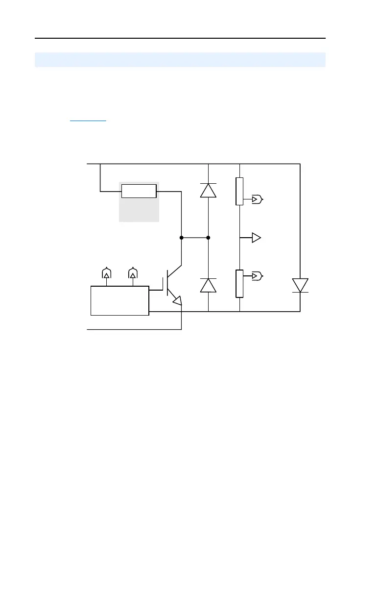
Figure 1.1 shows a simplified Dynamic Braking schematic.
Figure 1.1 Simplified Dynamic Brake Schematic
Chopper
The Chopper is the Dynamic Braking circuitry that senses rising DC bus
voltage and shunts the excess energy to the Dynamic Brake Resistor. A
Chopper contains three significant power components:
The Chopper Transistor is an Isolated Gate Bipolar Transistor (IGBT).
The Chopper Transistor is either ON or OFF, connecting the Dynamic
Brake Resistor to the DC bus and dissipating power, or isolating the
resistor from the DC bus. The most important rating is the collector
current rating of the Chopper Transistor that helps to determine the
minimum resistance value used for the Dynamic Brake Resistor.
Dynamic Brake Components
Signal
Common
Dynamic
Brake
Resistor
Chopper
Transistor
Chopper Transistor
Voltage Control
To
Voltage
Control
To
Voltage
Control
– DC Bus
+ DC Bus
To
Voltage Dividers
Voltage
Divider
Voltage
Divider
FWD
FWD

 Loading...


