Chapter 2
Detailed Drive Operation
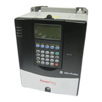
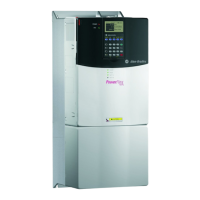
This chapter explains PowerFlex drive functions in detail. Explanations are
organized alphabetically by topic. Refer to the Table of Contents for a
listing of topics.
Accel Time [Accel Time 1, 2]
The Accel Time parameters set the rate at which the drive ramps up its
output frequency after a Start command or during an increase in command
frequency (speed change). The rate established is the result of the
programmed Accel Time and the Minimum and Maximum Frequency, as
follows:
Two Accel Times exist to allow the user to change acceleration rates “on the
fly” via PLC command or Digital Input. The selection is made using the 1st
/ 2nd Accel inputs shown below or a similar pattern of Accel Time select
bits in the Logic Control word used via PLC communications.
Times are adjustable in.1 second increments from 0.0 seconds to 3600.0
seconds.
In its factory default condition, when no Accel select inputs are closed and
no Accel Time bits are “1”, the default acceleration time is Accel Time 1
and the rate is determined as above.
AC Supply Source
Considerations
PowerFlex 700 drives are suitable for use on a circuit capable of delivering
up to a maximum of 200,000 rms symmetrical amperes, 600V.
If a system ground fault monitor (RCD) is to be used, only Type B
(adjustable) devices should be used to avoid nuisance tripping.
Maximum Frequency – Minimum Frequency
Accel Time
= Accel Rate
!
ATTENTION: To guard against personal injury and/or equipment
damage caused by improper fusing or circuit breaker selection, use
only the recommended line fuses/circuit breakers specified in
Tables
2.O through 2.S.

 Loading...


