2-126 Process PI Loop
If the application is Process Control, typically these limits would be set to
the maximum allowable frequency setting. This allows the PI regulator to
control over the entire required speed range.
If the application is Process Trim, large trim corrections may not be
desirable and the limits would be programmed for smaller values.
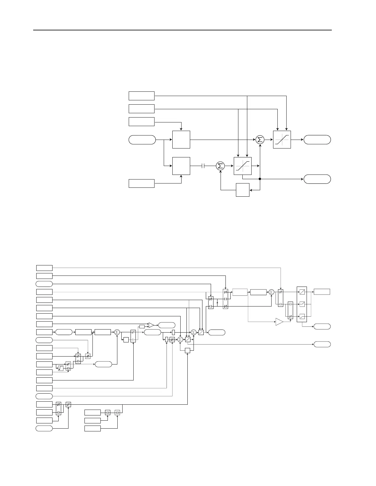
Output Scaling
The output value produced by the PI is displayed as ±100.00. Internally this
is represented by ±32767 which corresponds to maximum frequency.
Figure 2.15 Process PI Block Diagram
PI NegLmt
PI Kp
PI Ki
+
+
+
+
In Limit
PI PosLmt
*
*
PI_Status
.Hold
PI Error
Z
-1
PI Output
+
+
+
+
z
-1
*
*
PI Fbk
PI Error
PI Output
PI Ref
PI Cmd
Linear
Ramp
-
+
-
Linear Ramp
& S-Curve
Spd Ramp
Spd Cmd
≥
0
+
+
Zclamped
In Limit
PI XS Error
≥
abs
PI_Config
.Exclusive
Current Limit
or Volt Limit
Spd Cmd
*(PI Ref Sel)
*(PI Fbk Sel)
PI Kp
PI Ki
PI Neg Limit
PI Pos Limit
PI_Status
.Hold
Spd Ref
PI_Config
.RampCmd
PI_Status
.Enabled
PI_Config
.Invert
PI_Config
.Sqrt
0
PI_Config
.Exclusive
PI_Status
.Enabled
PI_Config
.ZeroClamp
PI ExcessErr
PI_Config
.PreloadCmd
Preload Value
PI_Status
.Enabled
Spd Cmd
+32K
0
-32K
0
+32K
-32K

 Loading...


