2-128 Reflected Wave
over-voltage transient greater than 2 pu. The amplitude of the double pulsed
motor over-voltage is determined by a number of variables. These include
the damping characteristics of the cable, bus voltage, and the time between
pulses, the carrier frequency, modulation technique, and duty cycle.
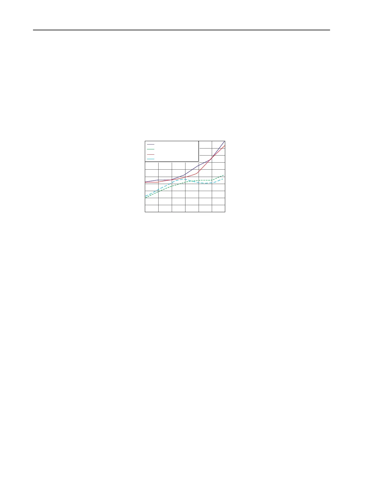
The plot below shows the per unit motor over-voltage as a function of cable
length. This is for no correction versus the modulation correction code for
varied lengths of #12 AWG PVC cable to 600 feet for a 4 kHz and 8 kHz
carrier frequencies. The output line-to-line voltage was measured at the
motor terminals in 100 feet increments.
Without the correction, the over-voltage increases to unsafe levels with
increasing cable length for both carrier frequencies.
The patented modulation correction code reduces the over-voltage for both
carrier frequencies and maintains a relatively flat over-voltage level for
increasing cable lengths beyond 300 feet.
No Correction vs Correction Method at 4 kHz and 8 kHz Carrier
Frequencies - Vbus = 650, fe = 60 Hz
Cable Length (Feet)
per Unit Vout/Vbus
1.6
1.7
1.8
1.9
2
2.1
2.2
2.3
2.4
2.5
2.6
1000 200 400 600300 500
No Correction 4 kHz Carrier
Corrected 4 kHz Carrier
No Correction 8 kHz Carrier
Corrected 8 kHz Carrier

 Loading...


