2-140 Speed Control Speed Mode Speed Regulation
Figure 2.16 Rotor Speed with/without Slip Compensation
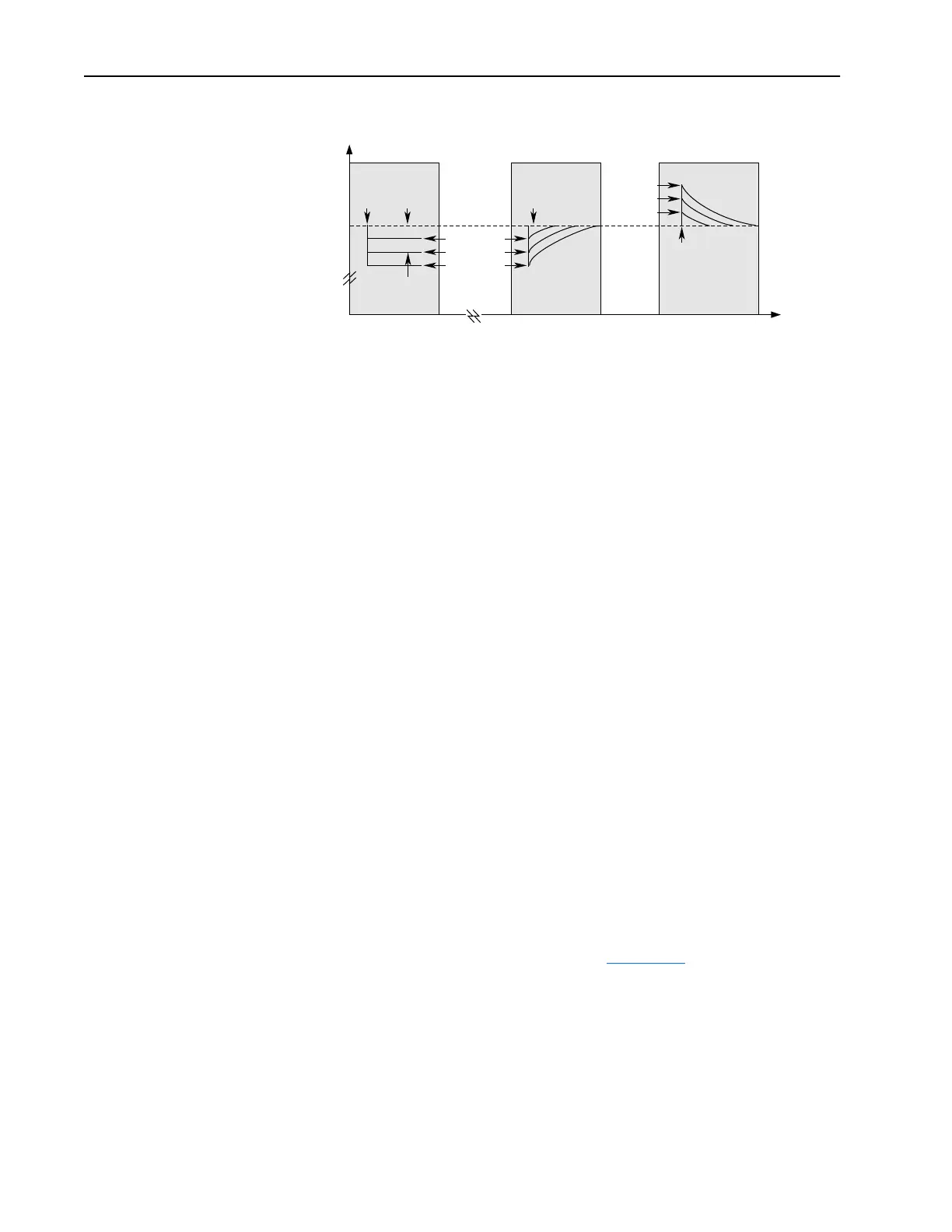
Without slip compensation active, as the load increases from no load to
150% of the motor rating, the rotor speed decreases approximately
proportional to the load.
With slip compensation, the correct amount of slip compensation is added
to the drive output frequency based on motor load. Thus, the rotor speed
returns to the original speed. Conversely, when the load is removed, the
rotor speed increases momentarily until the slip compensation decays to
zero.
Motor nameplate data must be entered by the user in order for the drive to
correctly calculate the proper amount of slip compensation. The motor
nameplate reflects slip in the rated speed value at rated load. The user can
enter the Motor Nameplate RPM, Motor Nameplate Frequency, the Motor
Nameplate Current, Motor Nameplate Voltage, and Motor Nameplate HP/
kW and during commissioning the drive calculates the motor rated slip
frequency and displays it in [Slip RPM @ FLA]. The user can adjust the
slip compensation for more accurate speed regulation, by increasing or
decreasing [Slip RPM @ FLA] value.
Internally, the drive converts the rated slip in RPM to rated slip in
frequency. To more accurately determine the rated slip frequency in hertz,
an estimate of flux current is necessary. This parameter is either a default
value based on motor nameplate data or the auto tune value. The drive
scales the amount of slip compensation to the motor rated current. The
amount of slip frequency added to the frequency command is then scaled by
the sensed torque current (indirect measurement of the load) and displayed.
Slip compensation also affects the dynamic speed accuracy (ability to
maintain speed during “shock” loading). The effect of slip compensation
during transient operation is illustrated in
Figure 2.17. Initially, the motor is
operating at some speed and no load. At some time later, an impact load is
applied to the motor and the rotor speed decreases as a function of load and
inertia. And finally, the impact load is removed and the rotor speed
increases momentarily until the slip compensation is reduced based on the
applied load.
Slip Compensation
Active
Slip Compensation
Inactive
Time
Rotor Speed
0
0
Load
Applied
Load
Applied
No Load
Slip @
F.L.A.
0.5 p.u. Load
1.0 p.u. Load
1.5 p.u. Load
0.5 p.u. Load
1.0 p.u. Load
1.5 p.u. Load
Slip Compensation
Active
Load
Removed

 Loading...


