Speed Control Speed Mode Speed Regulation 2-141
When slip compensation is enabled the dynamic speed accuracy is
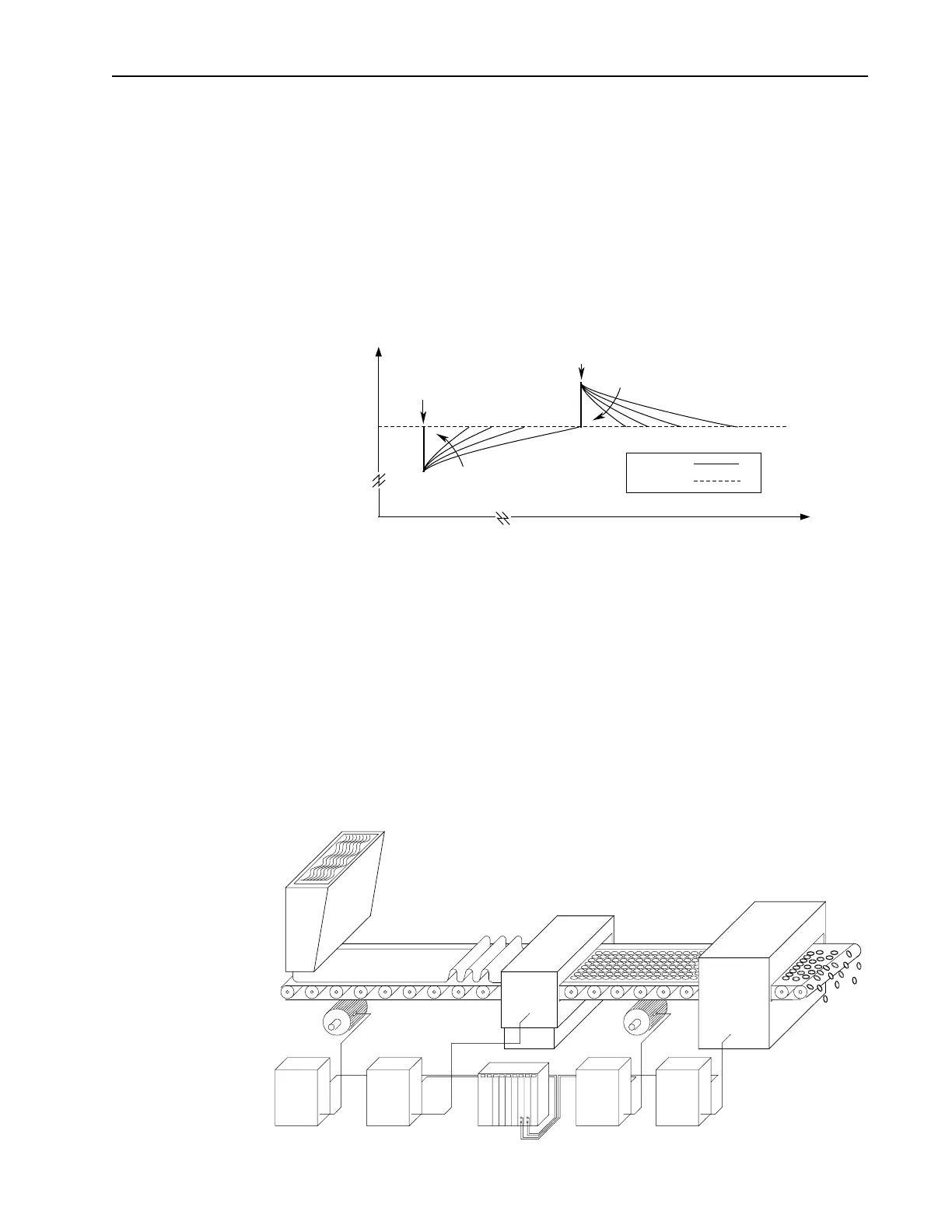
dependent on the filtering applied to the torque current. The filtering delays
the speed response of the motor/drive to the impact load and reduces the
dynamic speed accuracy. Reducing the amount of filtering applied to the
torque current can increase the dynamic speed accuracy of the system.
However, minimizing the amount of filtering can result in an unstable
motor/drive. The user can adjust the Slip Comp Gain parameter to decrease
or increase the filtering applied to the torque current and improve the
system performance.
Figure 2.17 Rotor Speed Response Due to Impact Load and Slip Com Gain
Application Example - Baking Line
The diagram below shows a typical application for the Slip Compensation
feature. The PLC controls the frequency reference for all four of the drives.
Drive #1 and Drive #3 control the speed of the belt conveyor. Slip
compensation will be used to maintain the RPM independent of load
changes caused by the cutter or dough feed. By maintaining the required
RPM, the baking time remains constant and therefore the end product is
consistent.
With the Slip Compensation feature, the process will only require a new
speed reference when the product is changed. The user will not have to tune
the drive due to a different load characteristic.
Time
Speed
0
0
Impact Load
Applied
Impact Load
Removed
Increasing Slip
Comp Gain
Increasing Slip
Comp Gain
Rotor Speed
Reference
PowerFlex
Drive
PowerFlex
Drive
PowerFlex
Drive
PowerFlex
Drive
#1 #2 #4
5/40
#3
Dough Stress
Relief
Cookie Line
CUTTERS OVEN

 Loading...


