EasyManuals Logo

Allen-Bradley PowerFlex User Manual

Allen-Bradley PowerFlex
235 pages
To Next Page IconTo Next Page
To Previous Page IconTo Previous Page
Page #182 background imageLoading...
Page #182 background image
2-160 Stop Modes
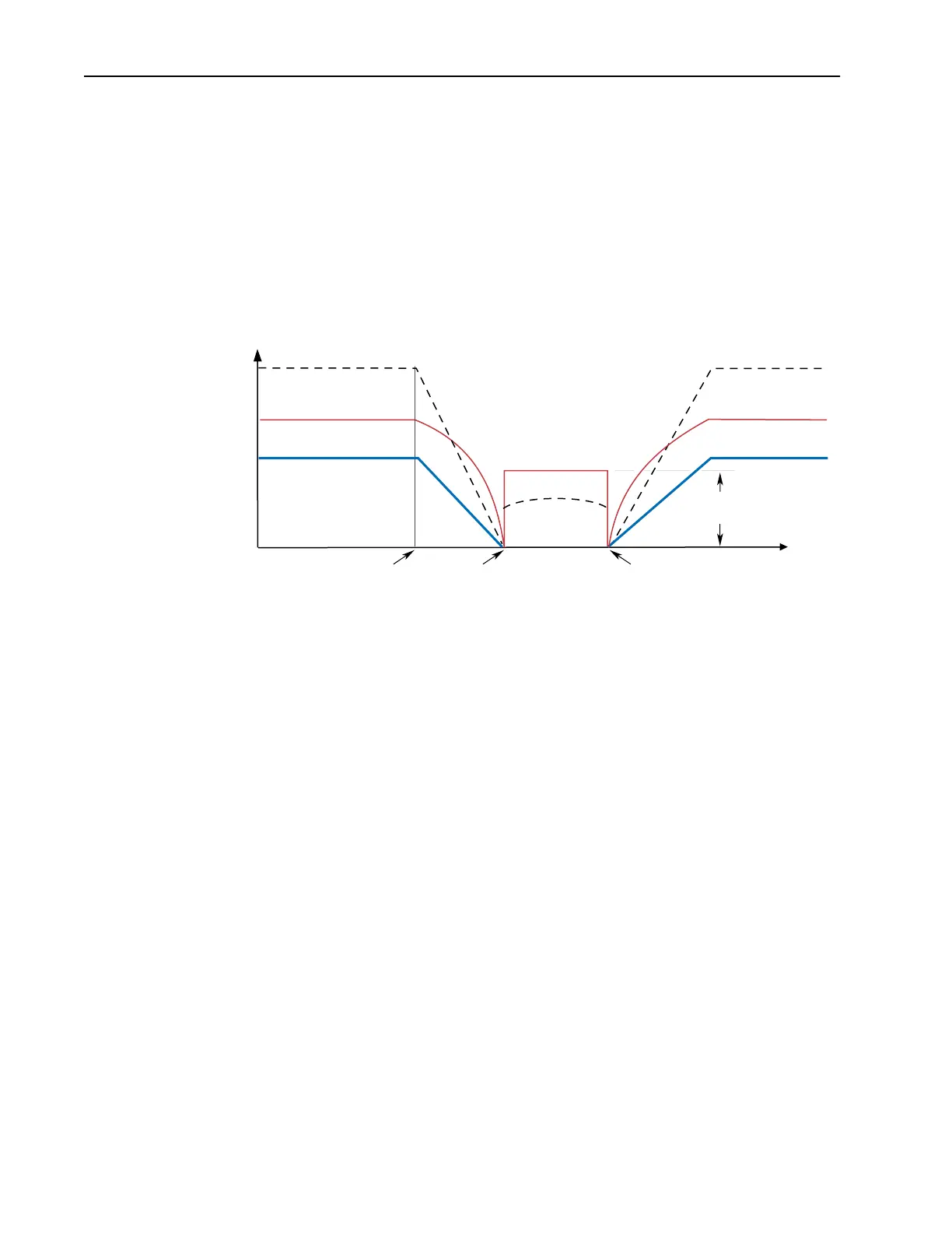
5. Ramp To Hold is selected by setting [Stop Select x]. The drive will
ramp the frequency to zero based on the deceleration time programmed
into [Decel Time 1/2]. Once the drive reaches zero hertz, a DC Injection
holding current is applied to the motor. The level of current is set in [DC
Brake Level]. The DC hold is removed only by removing the “Enable”
input or by a valid start input.
Motor speed during and after the application of DC depends upon the
combination of the these two parameter settings, and the mechanical
system. The drive output voltage will be zero when the hold time is
finished.
DC
Hold Level
Time
Output Voltage
Output Voltage
Output Current
Output Current
Motor Speed
Output Voltage
Output Current
Motor Speed
Re-issuing a
Start Command
Stop
Command
Zero
Command
Speed

Table of Contents

Other manuals for Allen-Bradley PowerFlex

Questions and Answers:

Question and Answer IconNeed help?

Do you have a question about the Allen-Bradley PowerFlex and is the answer not in the manual?

Allen-Bradley PowerFlex Specifications

General IconGeneral
CategoryDC Drives
ManufacturerAllen-Bradley
SeriesPowerFlex
Communication OptionsEtherNet/IP, DeviceNet, ControlNet
Protection FeaturesOvercurrent, Overvoltage, Undervoltage, Overtemperature, Short Circuit
Enclosure TypeNEMA 1, NEMA 12, NEMA 4/4X
Operating Temperature0°C to 40°C (32°F to 104°F)
Storage Temperature-40°C to 70°C (-40°F to 158°F)
Humidity5% to 95% (non-condensing)
AltitudeUp to 1000m (3280 ft) without derating

Related product manuals