Analog Outputs 2-21
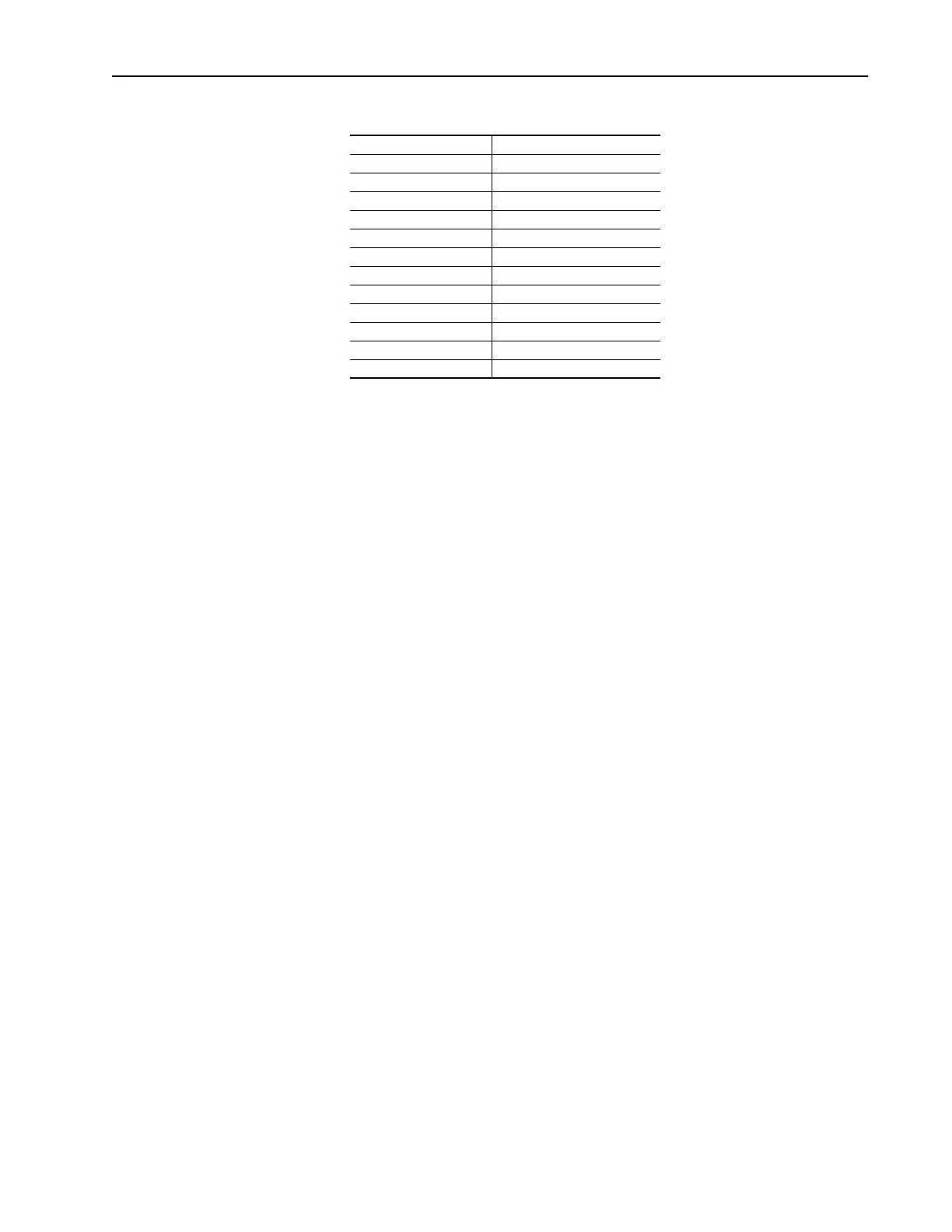
Table 2.C Software Filters
Analog output software filters are specified in terms of the time it will take
the output of the filter to move from 0% to various higher levels, given an
instantaneous step in the filter input from 0% to 100%. The numbers
describing filters in this document should be considered approximate; the
actual values will depend on implementation.
Filter A is a single pole digital filter with a 162ms time constant. Given a
0% to 100% step input from a steady state, the output of Filter A will take
500ms to get to 95% of maximum, 810 ms to get to 99%, and 910 ms to get
to 100%.
Quantity Filter
Output Frequency No extra filtering
Commanded Frequency No extra filtering
Output Current Filter A
Output Torque Current Filter A
Output Flux Current Filter A
Output Power Filter A
Output Voltage No extra filtering
DC Bus Voltage Filter A
PI Reference No extra filtering
PI Feedback No extra filtering
PI Error No extra filtering
PI Output No extra filtering

 Loading...


