6 Rockwell Automation Publication 1783-IN003D-EN-P - January 2019
Stratix 2000 Ethernet Unmanaged Switches
Enclosure Requirements
Clearance to front and rear panels must meet these conditions:
• Front-panel status indicators can be easily read.
• Access to ports is sufficient for unrestricted cabling.
• Power connector is within reach of the connection to the power source.
To prevent the switch from overheating, observe the following minimum clearances:
• Top and bottom: 51 mm (2.0 in.)
• Sides: 51 mm (2.0 in.)
• Front: 64mm (2.50 in.)
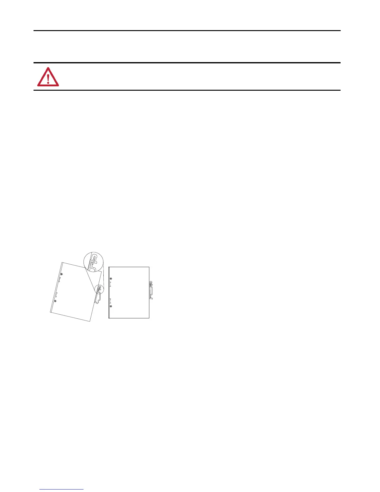
Mount the Switch
To mount the switch on a DIN rail, follow these steps.
1. Position the switch so that the top of the DIN rail mounting clip is slightly above the upper DIN rail edge.
2. With the bottom of the switch angled away from the panel, slide the switch downward until the mounting clip spring is behind the top edge
of the DIN rail.
3. Press the switch downward to compress the spring.
4. Press the bottom of the switch toward the panel until the clip locks into place over the bottom edge of the DIN rail.
WARNING: When used in a Class I, Division 2, hazardous location, this equipment must be mounted in a suitable enclosure with proper wiring method that
complies with the governing electrical codes.
32313-M

 Loading...


