Rockwell Automation Publication 1783-IN003D-EN-P - January 2019 9
Stratix 2000 Ethernet Unmanaged Switches
Connect the Power Supply
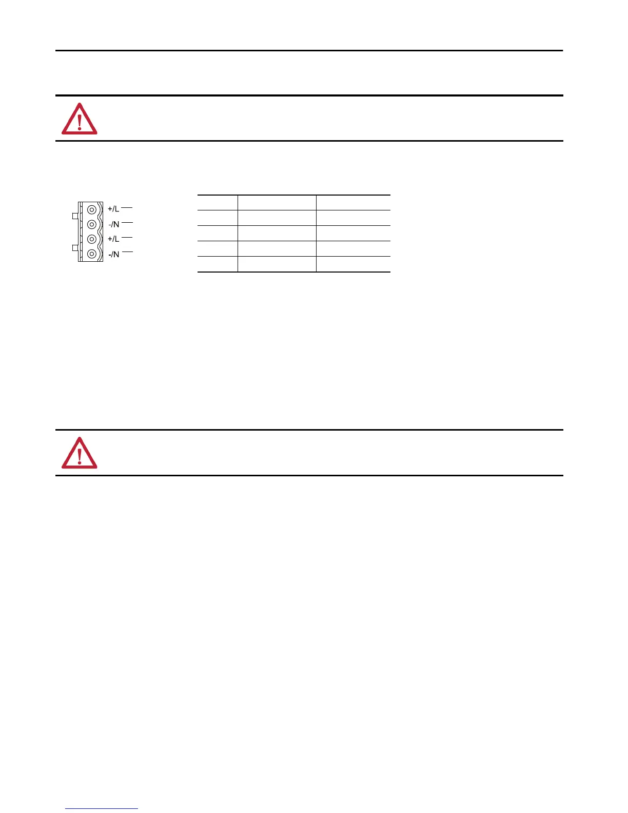
There is a power terminal connector on the top of the device. You must connect the power wires to the power terminal connector to provide power
for the device. The switch supports a redundant power supply with 4-pin, 5.08mm-spacing plug-in terminal block.
.
To connect the power supply to the switch, follow these steps.
1. Disconnect the power terminal connector on top of the switch.
2. Insert the power wires into the power terminal connector.
For proper polarity of the power wiring, use the cable pinout above or the diagram on the switch label.
3. Tighten the power connector by using a screwdriver.
4. Plug the power terminal connector back into the device.
Confirm Installation
Before you install the switch in its final location, power on the switch and verify the following:
• The port status indicators flash for a short time.
• The PWR1 or PWR2 status indicator is on continuously.
Remove the Switch from a DIN Rail
To remove the switch from a DIN rail, follow these steps.
1. Gently push the switch downward to compress the mounting clip spring.
2. Rotate the bottom of the switch away from the DIN rail until the bottom of the mounting clip is clear of the lower rail.
3. Lift the switch up until the mounting clip and springs clear the upper DIN rail.
WARNING: When you connect or disconnect the removable terminal block (RTB) with field side power applied, an electric arc can occur. This could cause an
explosion in hazardous location installations.
WARNING: When you change switch settings while power is on, an electric arc can occur. This could cause an explosion in hazardous location installations.
Be sure that power is removed or the area is nonhazardous before proceeding.
Pin For DC Wiring For AC Wiring
4 PWR2: + PWR2: L
3 PWR2: - PWR2: N
2 PWR1: + PWR1: L
1 PWR1: - PWR1: N
4
3
2
1
PWR2
PWR1

 Loading...


