Multi-Axis Coordinated Motion Instructions
432 Rockwell Automation Publication MOTION-RM002H-EN-P-February 2018
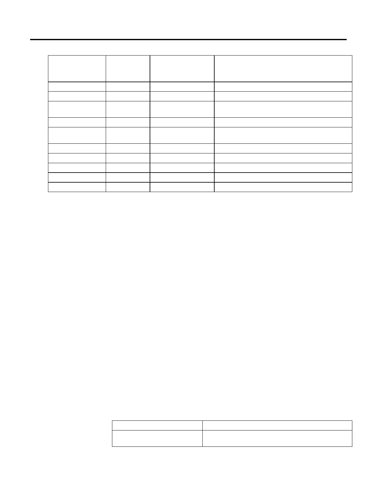
Referenced Error Code and
Number
Extended Error
Numeric Indicator
Instruction Parameter Description
Parameter Out Of Range (13) 0 Coordinate System Number of primary axes is not 2 or 3.
Parameter Out Of Range (13) 2 Move Type Move Type is either less than 0 or greater than 1.
Parameter Out Of Range (13) 3 Position The position array is not large enough to provide positions for all the axes in
the coordinate system.
Parameter Out Of Range (13) 4 Circle Type Circle Type is either less than 0 or greater than 4.
Parameter Out Of Range (13) 5 Via/Center/Radius The size of the Via/Center array is not large enough to provide positions for all
of the axes in the defining via/center point.
Parameter Out Of Range (13) 6 Direction Direction is either less than 0 or greater than 3.
Parameter Out of Range (13) 7 Speed Speed is less than 0.
Parameter Out of Range (13) 9 Accel Rate Accel Rate is less than or equal to 0.
Parameter Out of Range (13) 11 Decal Rate Decel Rate is less than or equal to 0.
Parameter Out of Range (13) 14 Termination Type Termination Type is less than 0 or greater than 3.
For the Error Code 54 – Maximum Deceleration Value is Zero, if the Extended
Error returns a positive number (0-n) it’s referring to the offending axis in the
coordinate system. Go to the Coordinate System Properties General Tab and look
under the Brackets ([ ])column of the Axis Grid to determine which axis has a
Maximum Deceleration value of 0. Click on the ellipsis button next to the
offending axis to access the Axis Properties screen. Go to the Dynamics tab and
make the appropriate change to the Maximum Deceleration Value. If the
Extended Error number is -1, this means the Coordinate System has a Maximum
Deceleration Value of 0. Go to the Coordinate System Properties Dynamics Tab
to correct the Maximum Deceleration value.
MCCM Changes to Status Bits:
Status bits provide a means for monitoring the progress of the motion instruction.
There are three types of Status bits that provide pertinent information.
• Axis Status bits
• Coordinate System
• Coordinate Motion
When the MCCM instruction initiates, the status bits undergo the following
changes.
Axis Status Bits
Bit Name Meaning
CoordinatedMotionStatus Sets when the MCCM instruction executes and is cleared when the instruction
completes.
 Loading...


