Multi-Axis Coordinated Motion Instructions
Rockwell Automation Publication MOTION-RM002H-EN-P-February 2018 511
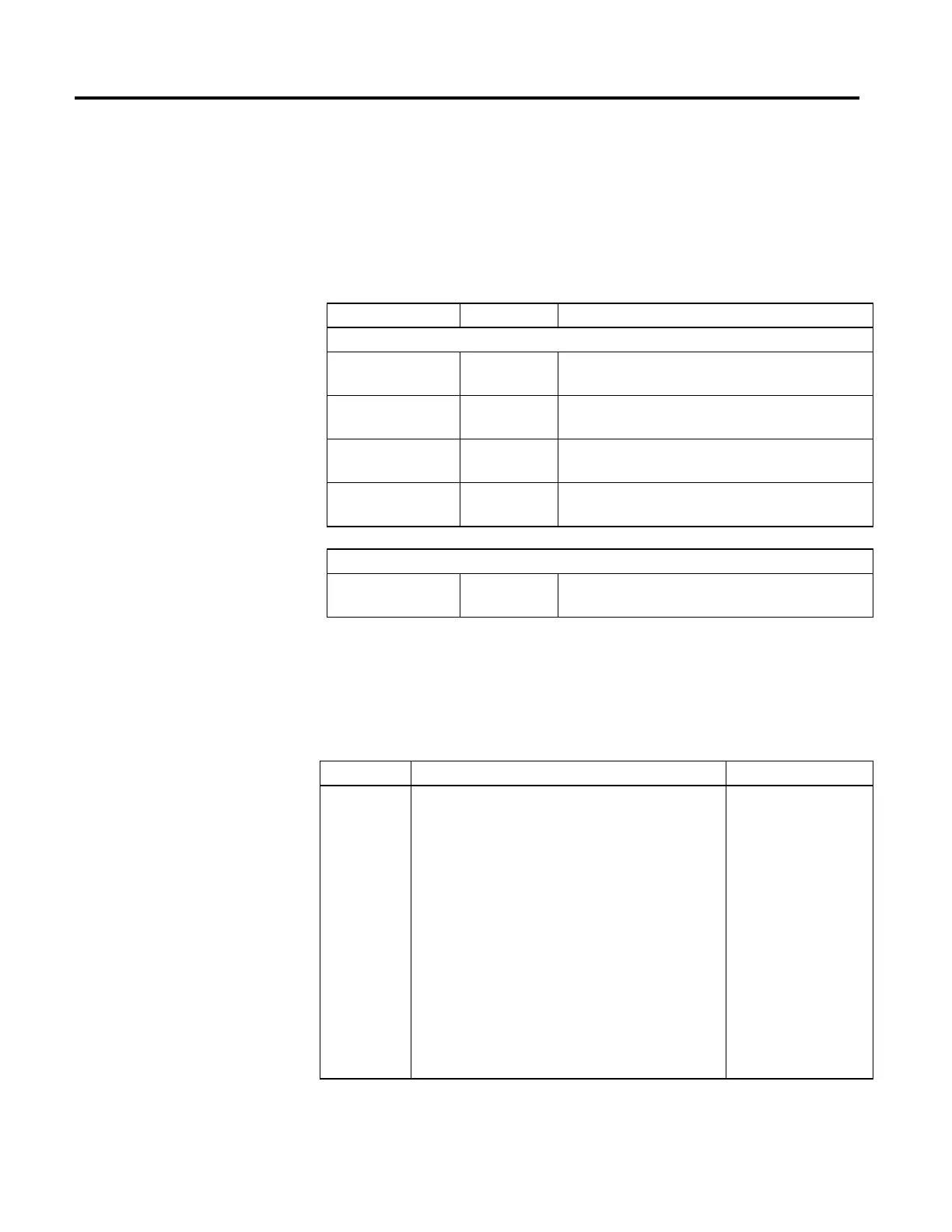
The middle column of the table below identifies which parameter is applicable to
each coordinate system motion instruction, that is, to MCLM and MCCM.
Before any of the parameters identified in the first column below may be used in
the MCLM or MCCM instruction, you must execute an MDCC instruction and
it must be active (IP bit is set).
Parameter Instruction Mode
Input Parameters
Lock Direction
MCLM,
MCCM
Master Driven Only
Lock Position
MCLM,
MCCM
Master Driven Only
Command Tolerance
MCLM,
MCCM
Master Driven and Time Driven
Event Distance
MCLM,
MCCM
All modes (Master Driven or Time Driven)
Output Parameter
Calculated Data
MCLM,
MCCM
All modes (Master Driven, Time Driven, and Timed Based)
Input Parameters
The following table describes the input parameters.
Lock Direction
Data Type Description Valid Default Values
Immediate
This parameter is used for both Time Driven and Master Driven Mode.
The controlling axis is the Master Axis (axis is programmed in the MDCC
command) for Master Driven Mode and the axis that is programmed in
the motion instruction (for example, MCLM) for Time Driven Mode.
The first word of the Lock Direction enumeration definition (see
enumeration table below) identifies the lock type as either:
• Immediate (lock is performed immediately), or
• Position (lock is performed when the Master Axis crosses the
specified Lock Position).
The second word of the enumeration specifies the direction in which
the Master Axis has to be moving when it crosses the Lock Position for
the lock to take effect.
For an MCLM and MCCM instruction, the Slave Coordinate System
always moves in one direction - its programmed direction - while it
follows the Master Axis, regardless of the direction of the Master Axis.
If the Master reverses, the Slave Coordinate System stops.
Valid = 0-4
Default = None
(Enumeration 1-4 are currently
not allowed in Time Driven
mode.)
For Master Driven Mode, the enumerations are as follows:
(Forward is positive velocity, reverse is negative velocity.)
The enumerations table is below.
Input and Output Parameters
Structure for Coordinate System
Motion Instructions