Common attributes for Motion instructions
666 Rockwell Automation Publication MOTION-RM002H-EN-P-February 2018
• x = 0;
• }
• z = y + x;
Or another example:
• x = x + some_tiny_number;
• if (x >= 100)
• {
• z = z + 100;
• x = x - 100; // there might be a tiny remainder
• }
When using LINT data types, many limitations apply. A LINT data type cannot
be used in most instructions. LINT data type is:
• A 64-bit word.
• Not supported by products that use 32-bit words.
• Not supported in most instructions.
Tip:
LINTs can only be used with copy (COP, CPS) instructions. They are used with the
CST/WallClock Time attribute, time synchronization and Add-On Instructions. You
cannot add, subtract, multiply, or divide this tag type.
When using LINT data types, consider the following descriptions when these
issues occur.
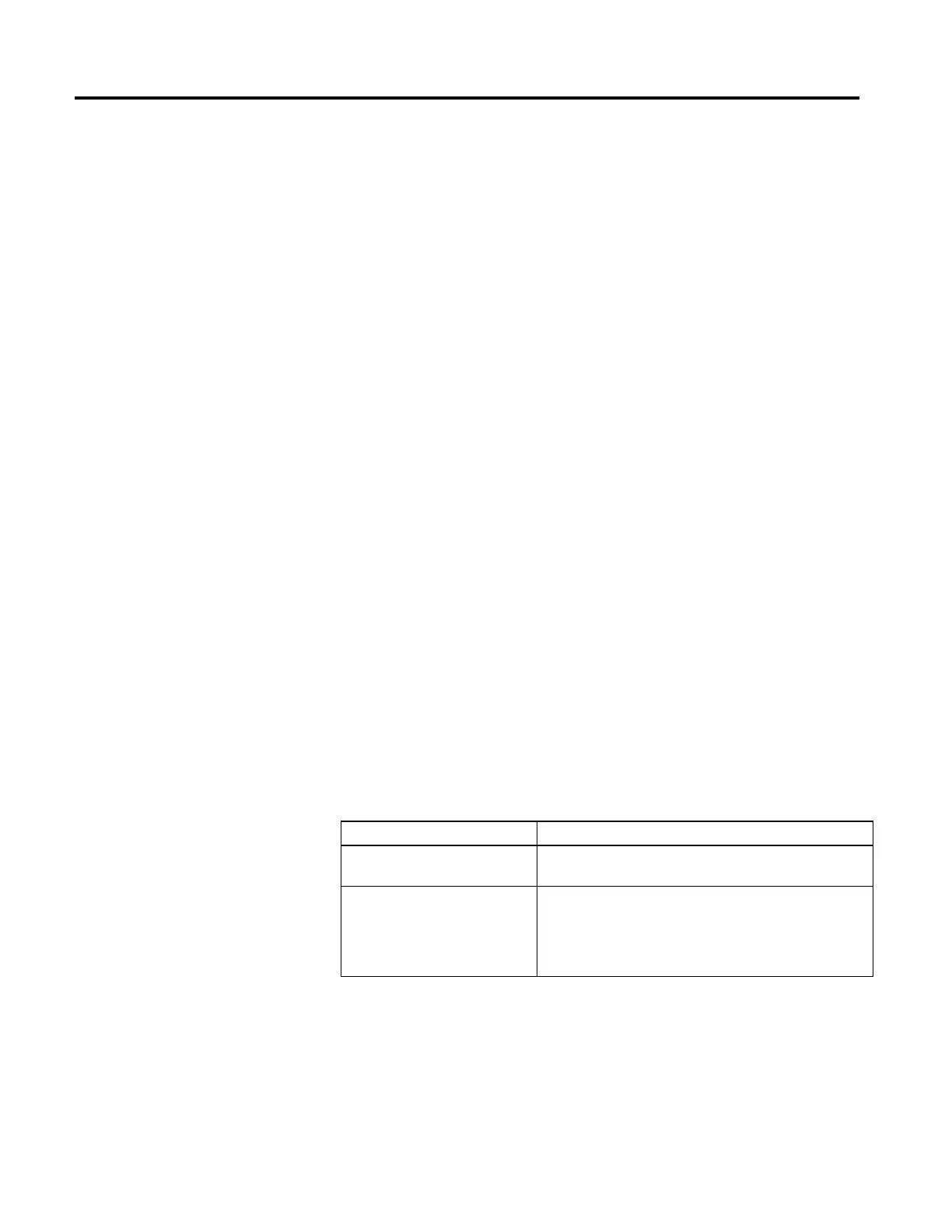
How to Description
Move/copy two double-integer DINT values
into one LINT
Create a double integer array of two elements, total of 64 bits (that is,
DINT[2], which can then be copied into one long integer.
Correct Date/Time Display error When a tag has a negative value, it cannot be displayed as Date/Time. In
the tag editor, check whether the value is negative by changing the style of
the tag from Date/Time to Binary. When the most significant bit (leftmost
one) is 1, the value is negative and therefore cannot be displayed as a Date
or Time.
 Loading...


