Multi-Axis Coordinated Motion Instructions
Rockwell Automation Publication MOTION-RM002H-EN-P-February 2018 469
Coordinated Transform This stop type cancels the transforms associated with the specified coordinate system. All transform-related motion stops on
all associated target coordinate systems. However, source coordinate axes will continue to move as instructed.
Example
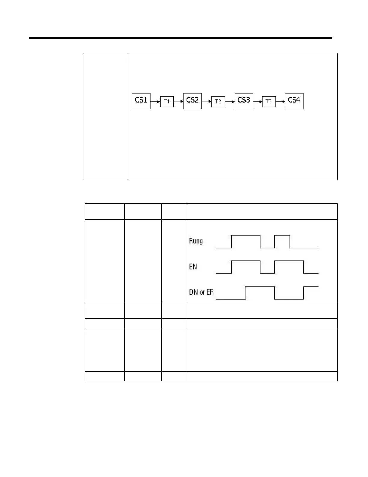
If four coordinate systems are linked via three transforms. And the first coordinate system (CS1) is the source and is
processing commanded motion.
Executing an MCS instruction on CS2 and using a stop type of coordinated transform results in:
• Transforms T1 and T2 are canceled.
• Transform T3 stays active.
• the axes in CS1 stay in motion.
• the axes in Coordinate Systems CS2 and CS3 stop via the deceleration rate selected in the MCS instruction or the
maximum coordinate deceleration rate.
• the axes in CS4 follow the respective CS3 axes.
In an Motion Axis Stop (MAS) instruction, a stop type of all also cancels transforms.
MOTION_INSTRUCTION Data Type
To see if Check if this bit is
on
Data Type Notes
The rung is true EN BOOL Sometimes the EN bit stays on even if the rung goes false. This happens if the rung goes
false before the instruction is done or an error has occurred.
The stop was
successfully initiated
DN BOOL
An error happened ER BOOL
The axis is stopping IP BOOL Any of these actions ends the MCS instruction and turns off the IP bit:
• The coordinate system is stopped.
• Another MCS instruction supersedes this MCS instruction.
• Shutdown instruction.
• Fault Action.
The axis is stopped PC BOOL The PC bit stays on until the rung makes a false-to-true transition.
Master Driven Speed Control (MDSC) and the MCS Instruction
If an MCS is issued when in Master Driven Mode, a switch is made to Time
Driven Mode and the axes are stopped in Time Driven Mode. MCS All resets the
IP bit of the Master Driven Coordinate Control (MDCC) instruction. Other
stop types do not reset the IP bit.
 Loading...


