EasyManuals Logo

Allied Telesis AT-8016F/MT User Manual

Allied Telesis AT-8016F/MT
116 pages
To Next Page IconTo Next Page
To Previous Page IconTo Previous Page
Page #56 background imageLoading...
Page #56 background image
Installation
56
Figure 21. Optical Bore and Ferrule of GBIC Module
Note
Unnecessary removal and insertion of a GBIC can lead to premature
failure.
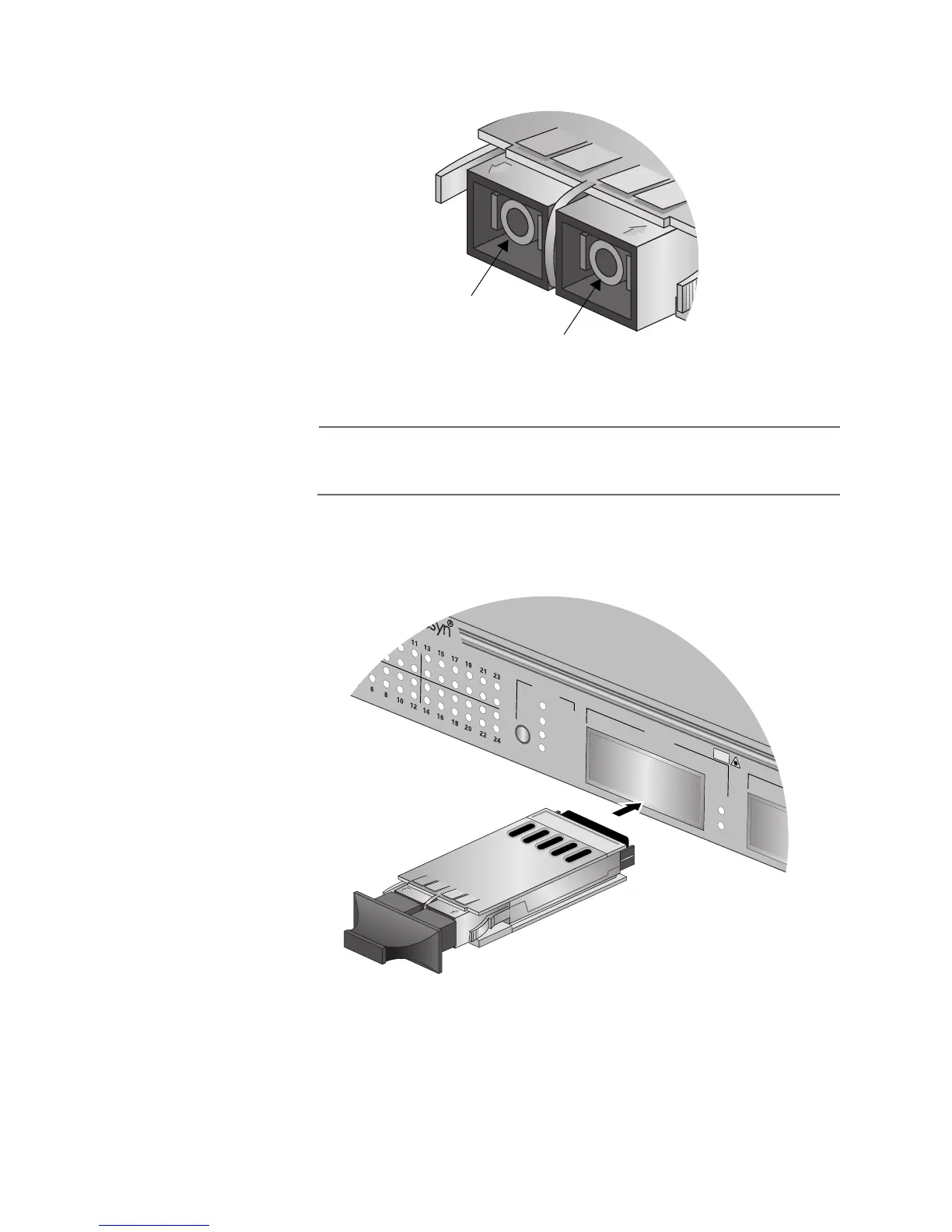
4. Slide the GBIC module into an expansion slot on the switch. The
GBIC module is completely seated in the slot when it clicks into
place.
Figure 22. Installing a GBIC Module
5. If you purchased two GBIC modules for the switch, repeat this
procedure to install the second module.
Ferrule
Bore
Link
Mode
Link
Mode
100
FULL
ACT
MODE
COL
LINK
MODE
PORT A
10Base-T /100Base-TX Fast Ethernet Switch
CLASS 1
LASER PRODUCT
DO NOT STARE
INTO BEAM

Table of Contents

Other manuals for Allied Telesis AT-8016F/MT

Questions and Answers:

Question and Answer IconNeed help?

Do you have a question about the Allied Telesis AT-8016F/MT and is the answer not in the manual?

Allied Telesis AT-8016F/MT Specifications

General IconGeneral
BrandAllied Telesis
ModelAT-8016F/MT
CategorySwitch
LanguageEnglish

Related product manuals