Installation
62
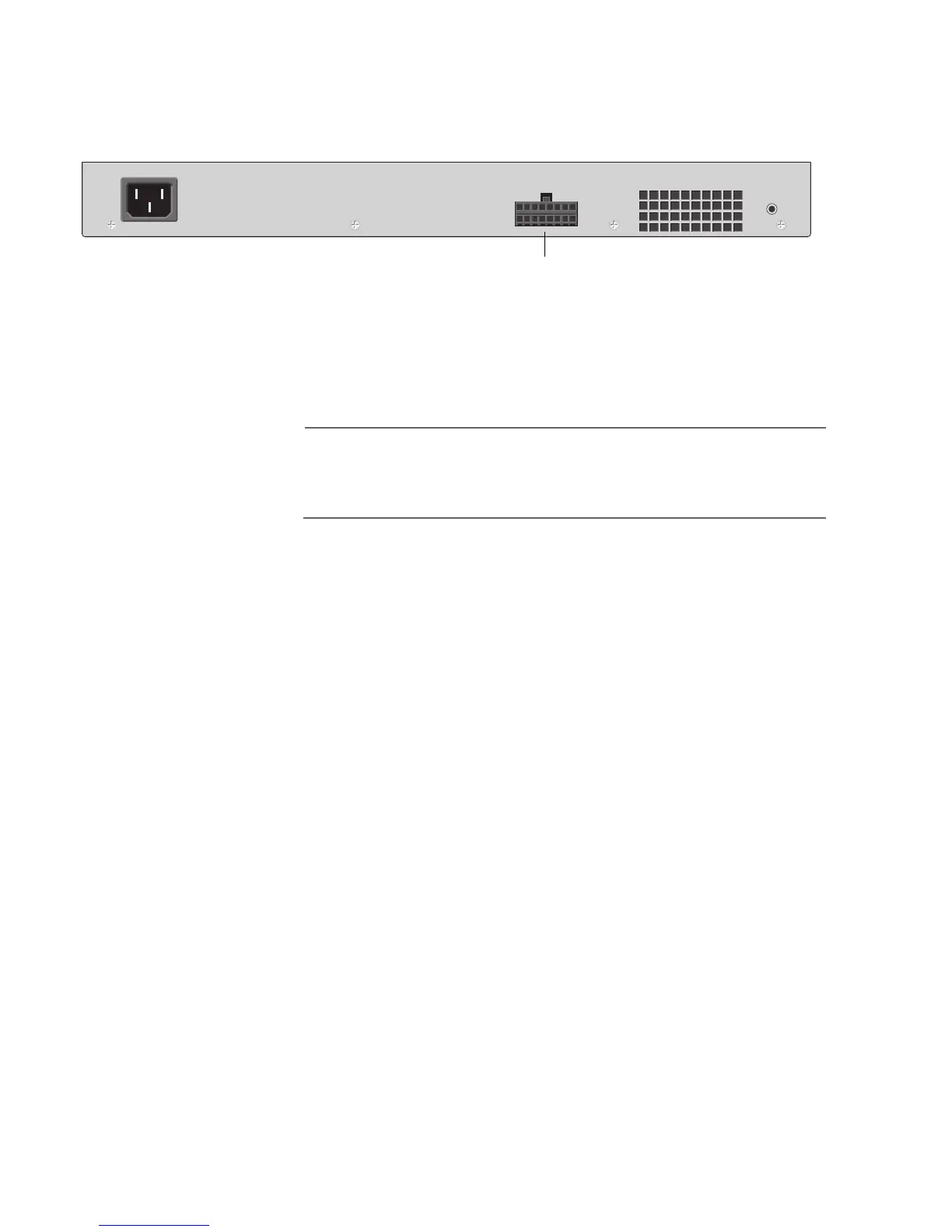
8. Connect the other end of the DC power cord to the RPS Input
connector on the back panel of the Ethernet switch. Refer to Figure
29 for the RPS Input connector.
Figure 29. Back Panel of the Ethernet Switch
9. Plug the AC power cord for the AT-RPS3004 into the AC connector
on the back panel of the unit. Refer to Figure 28 for the AC
connector.
Note
The AT-RPS3004 unit and Ethernet switches should be connected
to power outlets on separate circuits. This will protect the switches
from a loss of power should a power circuit fail.
10. Plug the other end of the AC power cord into a wall outlet.
11. Turn on the AT-RPS3004 using the switch on the back panel of the
unit. Refer to Figure 28 for the ON/OFF switch.
12. Make sure the LED on the front of the power supply is green.
RPS Input Connector for the DC Power Cord
RESET
 Loading...