Chapter 1: Technical Specifications
AT-iMG2400 Series Installation Guide 13
connected.
Consult the dealer or an experienced radio/TV technician for help.
This Class B digital apparatus complies with Canadian ICES-003.
Cet appareil numérique de la classe B est conforme à la norme NMB-003 du Canada.
Immunity: EN55024
Electrical Safety: UL60950 (
c
TUV
us
),CSA, C-TICK, CE
Power Cord Wiring
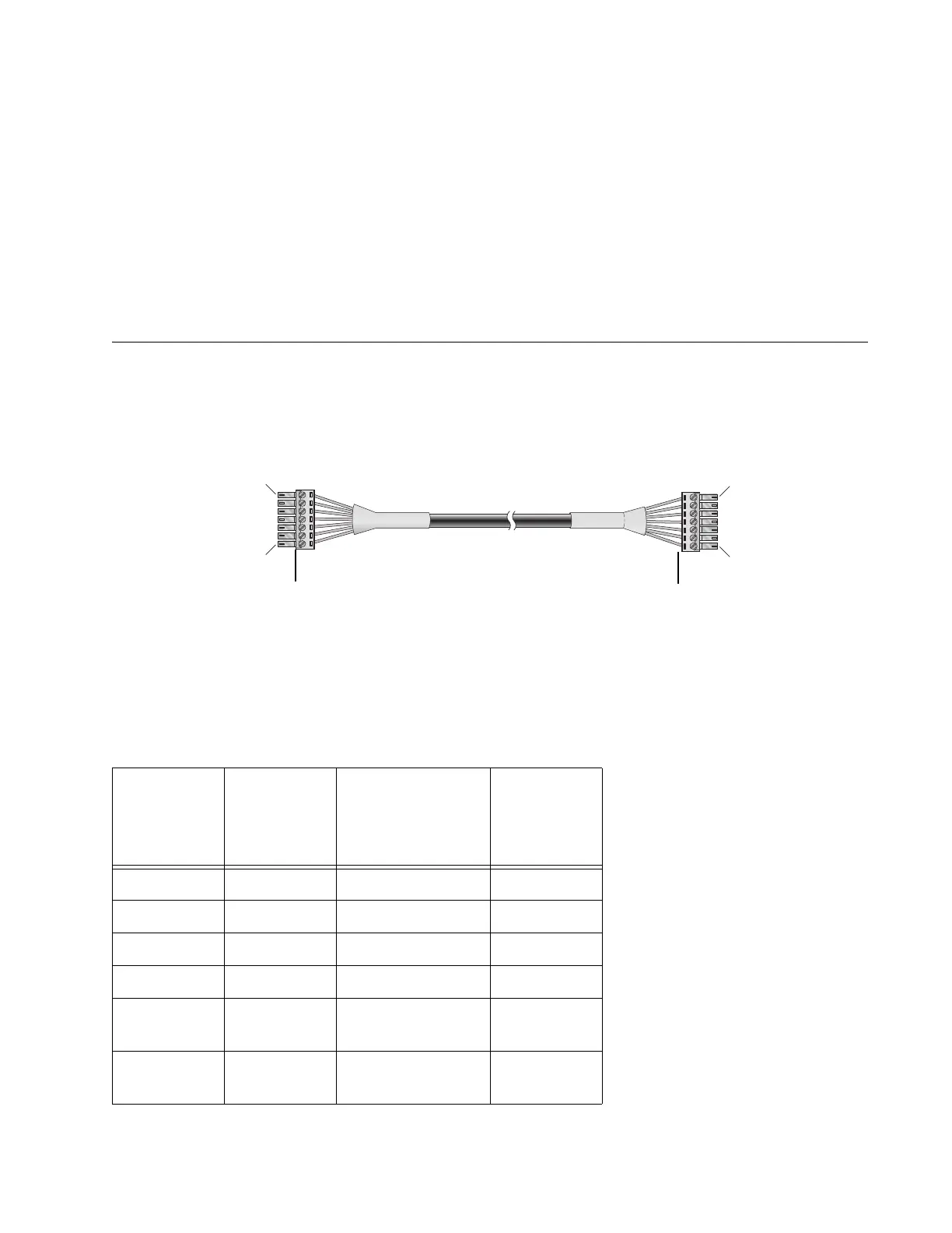
To wire the terminal block for the gateway to the terminal block for the power supply cord, refer to Figure 2
and Table 1.
Figure 2: Gateway Terminal Block to Power Cord Terminal Block Wiring Diagram
Table 1: Gateway Terminal Block to Power Cord Terminal Block
Wiring
Circuit
Gateway
Te r m i n a l
Block
Color
(* = determined
by Customer)
Power
Cord
Te r m i n a l
Block
+12VDC 1 RED 1
RET 2 BLACK 2
GND 3 GREEN 3
ON BATT 4 * 4
REPLACE
BATT
5* 5
BATT
MISSING
6* 6
iMG Terminal Block
Power Supply Terminal Block
 Loading...