Chapter 2: Installing the Gateway
AT-iMG2400 Series Installation Guide 19
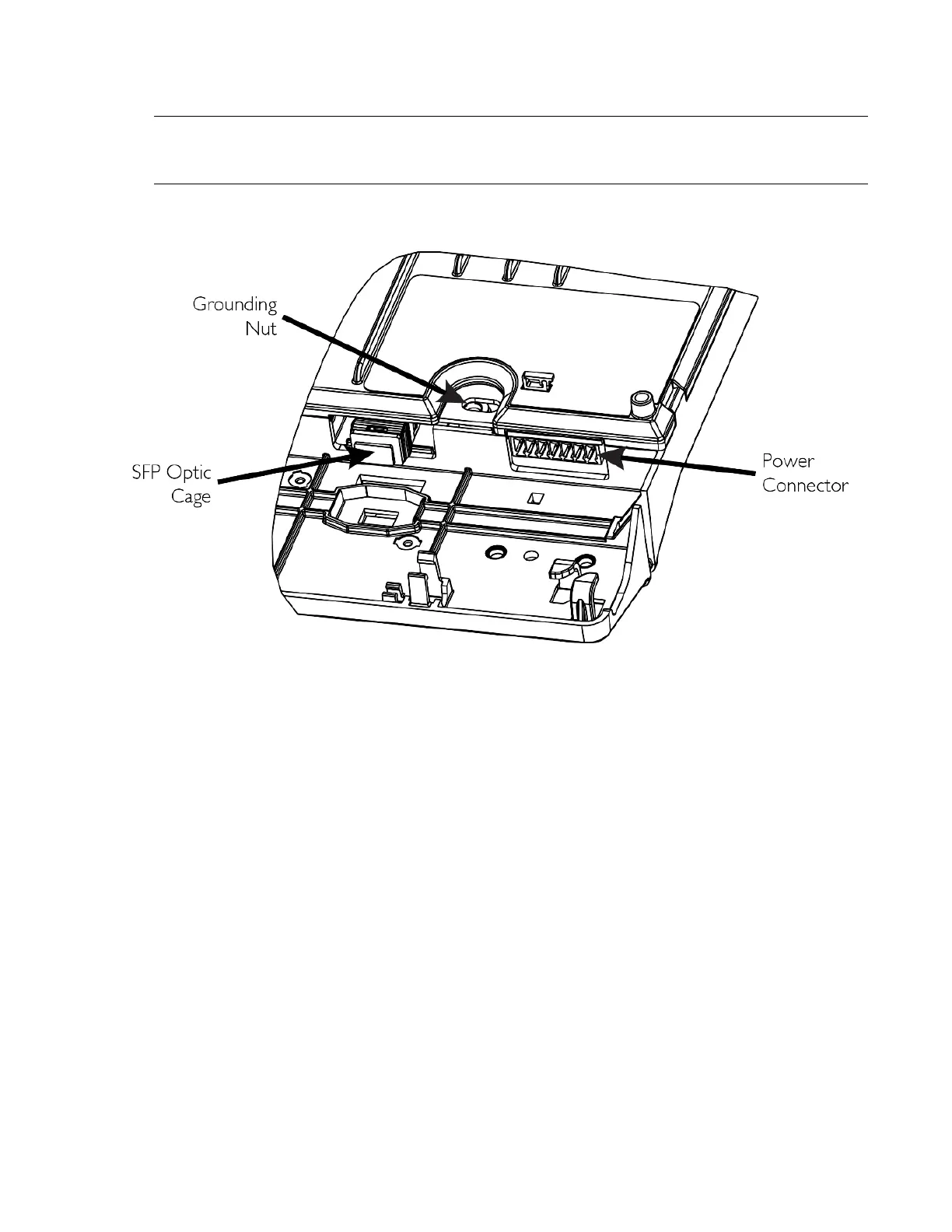
In the enclosure there are two cable entrances. The left entrance is for power, grounding, and the fiber
cables. The right is for all telephone and LAN cables. Refer to Figure 7.
Figure 6: Rear Connections
Note Slot Placement
Figure 7 shows the slot numbering for the grommets and the types of connections to use.
 Loading...