Chapter 2: Installing the Gateway
AT-iMG2400 Series Installation Guide 21
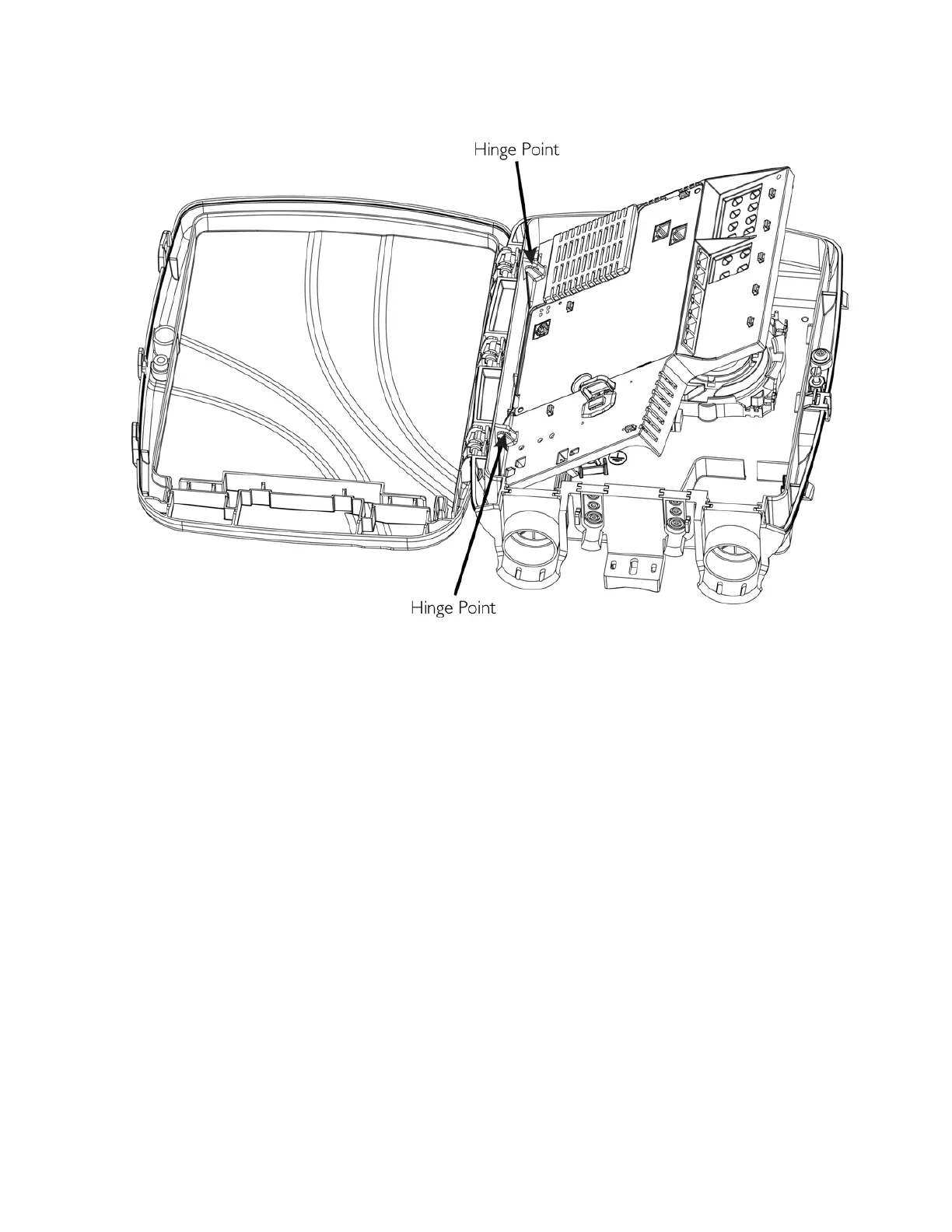
Figure 8: Snapping the gateway into the Enclosure
Connect the Power Cord
Allied Telesis sells a 15 ft. power cable (model number AT-iMG017). Alternatively, you can make custom
length power cables. The power connectors (7-pin terminal blocks) are supplied with the UPS and the
gateways. For lengths up to 30 ft., use wire with a minimum 18 AWG. Figure 2 on page 13 provides a detailed
wiring diagram.
To connect the power cord, perform the following procedure:
1. Note that the Enclosure has the fiber entrance configured and there is already a hole that has been
punched in the far left grommet.
2. Slide either end of the power cable through the far left grommet and into the back of the electronics unit.
3. Plug the terminal block into the DC power socket, as shown in Figure 9.
4. Tie-wrap the power cable, as shown below.
 Loading...