NOTE:RefertoFigure5–6forDrainPlugLocationsandFilter
Locations.
NOTE:Localconditions,severityofoperationordutycyclemay
requiremoreorlessfrequentuidchangeintervalsthatdiffer
fromthepublishedrecommendeduidchangeintervalsofAllison
Transmission.AllisonTransmissionrecommendsthatcustomersuse
uidanalysisastheprimarymethodfordetermininguidchange
intervals.Intheabsenceofauidanalysisprogramtheuidchange
intervalslistedinthechartsshouldbeused.
TherearethreemethodsrecommendedbyAllisonTransmissiontohelpyou
determinewhentochangetheuidandltersinyourAllisonTransmission.
Themethodsareasfollows:
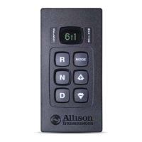
•WhenaPrognosticsindicatorbecomesactive(shownbyilluminating
theTRANSSERVICEindicatorintheselectorVFdisplay).
NOTE:Thestrippushbuttonselectorhasnodisplayandisnot
prognosticscapable.
•WhenrecommendationslistedintheFluidandFilterChangeInterval
Tablesaremet.RefertoTable5–6.
•Whenauidanalysisprogramindicatesauidchangeisnecessary.
Filterchangesmuststilloccurbasedoneitheroftheeventsoccurring
above.
NOTE:Calendar-basedchangeintervalsmuststillbeadheredtofor
bothuidandlterchangesevenifPrognosticshasnotindicatedthe
needforeitheruidorltermaintenance,unlessuidanalysisis
used.Ifmaintenanceisdonebecausetheuidorltersreachedthe
calendar-basedchangeinterval,theOMandFMshouldbemanually
resetatthattime.Referto5.9.6OILLIFEMONITOR(OM)and
5.9.7FILTERLIFEMONITOR(FM).
NOTE:AllisonTransmissionHighCapacityltersarerequiredin
ordertouseFMfeaturewithPrognosticsonmaintenanceschedule.
104

 Loading...


