24 - English - Translated from the original language Manual 6-1624970M - rev. 1 - 11/01/2023
4.8 - ANTENNA CONNECTION AND RADIO COMMUNICATION
WARNING
• Do not place the control unit inside metal containers.
• The maximum range can vary significantly in the presence of metal parts, in the presence of shielding
between the transmitter and the control unit or in the presence of other devices that communicate at the
same radio frequency.
# TERMINAL FUNCTION RATING
8 Antenna cable
Connect cable type RG58
9 Shield
The control unit is supplied with a standard antenna already connected.
INSTALLATION ADVICE
The RADIO LED on the board, allows to have a visual feedback of the amount of radio noise present
in the surroundings of the automation. The more the LED is fixed and the greater the disturbances
present.
In susceptible installations it is advisable to install an antenna at 433mhz. Install the external antenna
and its cables in a place protected from damage and/or vibration and where there are no obstacles
between the transmitters and the antenna.
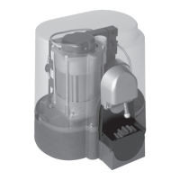
4.9 - ELECTRICAL CONNECTIONS BY THE MANUFACTURER
DANGER
• The operation of replacing the control unit can be operated only by authorized and highly qualified
personnel.
• Before carrying out such operations make sure to operate in the absence of voltage and in total safety.
The connections described in this section are already made during the factory assembly of the gear motor.
Refer to this table if you need to replace the control unit.
# TERMINAL FUNCTION RATING
1 GREY cable - Common (W)
Cable connection with SINGLE-phase electric
motor.
2 BLACK cable - Phase 1 (V)
3 BLUE cable - Phase 2 (U)
1 BLUE cables - Phase 1 (W)
Cable connection with THREE-PHASE electric
motor.
2 BLACK cables - Phase 2 (V)
3 WHITE cables - Phase 3 (U)
7 Earthing of the electronic board.
10 BROWN Cable - Common LIMIT SWITCH
Contact clean (voltage free) Normally Closed.
Signal LED Normally On.
16 RED cable - LSO limit switch contact
17 GREEN Cable - LSC limit switch contact
 Loading...