0180036-J0 Rev E Page 30
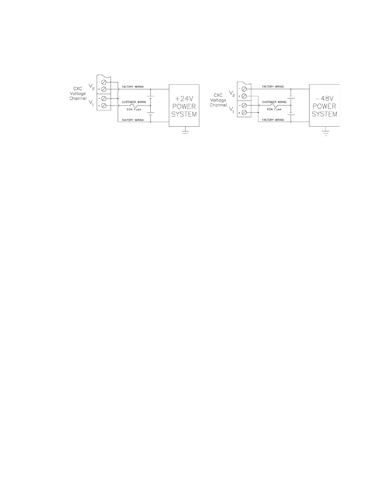
Figure 16: Connection Example: Midpoint Monitoring
9.5.2 Ground Fault Detection (HV-ADIO only)
V2 is also used for ground fault detection (GFD) (internally connected circuit). Ground fault is detected
when either terminal of V2 (system voltage that is normally connected to the battery string) is connected
to earth ground either directly or through some conductive means.
The GFD circuit will detect a fault current range of 0 to 15mA of current flowing from either Batt+ or Batt-
to earth. The GFD alarm threshold can be set in the CXC HP controller, see the software manual
(0350058-J0) for details.
The GFD circuit is also able to measure the fault resistance and report the value from 0Ω to 10Meg Ω.
The default setting for the alarm is OFF. When the GFD is disabled in OFF mode, the circuit is discon-
nected from earth and should not affect external ground fault measurements from other equipment.
The GFD is factory calibrated and cannot be re-calibrated.
9.6 Digital Inputs
The digital input channels (terminals 24 through 39 on the L-ADIO) are used to monitor various alarm
and control signals. All input channels are voltage activated and accept a bipolar (i.e. negative or posi-
tive) DC signal directly. Where terminations are made to bus voltages, ensure the terminations are
fused.
For the HV-ADIO, all input channels are contact closure activated and are low voltage only. There is no
connection to the bus voltage.
9.6.1 Connection Method - Low Voltage
Typical Alpha systems use the reset with Hot and trigger with Ground connection. The digital input is
wired in such a way that the Hot is wired directly into one of the input terminals; e.g., positive input for
+24V or negative input for –48V systems. The other input terminal is wired to the Ground (common) of
the system through a relay (dry contact – usually located on the equipment requiring monitoring). This
method allows the digital input to receive (or not receive) a Ground signal on an alarm.