0180036-J0 Rev E Page 35
9.7 Relay Outputs
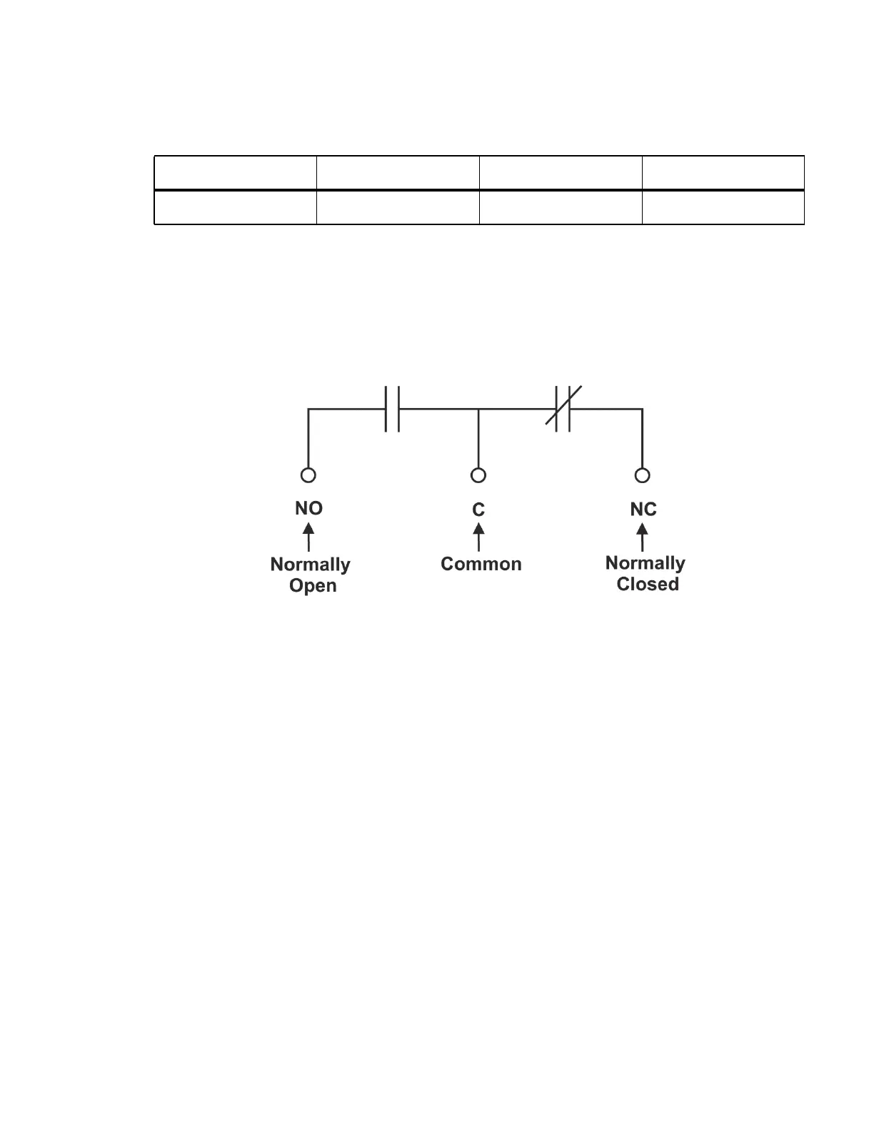
Terminals 4 to 21, and 64-81 provide 12 Form C contacts (NO, COM and NC) for extending various
alarm or control signals. Each relay output can be wired for NO and/or NC operation during an alarm or
control condition.
Figure 19: Relay Connections: De-energized State
Relays can be programmed to energize or de-energize during an alarm condition (for more details see
the CXC HP controller software manual). When the CXC HP reset button is pressed or power is lost, all
relays de-energize. Relay contacts may be used for LVD contactors (50W maximum).
9.7.1 System Fail Relay
On the CXC HP controller, terminals 4, 5, 6 provide connections for a system (supervisory) fail relay.
This fail-safe relay (i.e. it is de-energized during an alarm condition) can be wired for NO or NC opera-
tion.
9.7.2 LVD Control
The LVD control functions can be hardwired directly from the assigned relay output pins to the LVD
contactor panel. See Controls menu defaults in the software manual.
9.7.3 Additional I/O Expansion
Additional I/O peripherals may be added to the system if required to expand the number of I/O channels
required in an application.
9.8 Rectifier Connections
30 and 31; D4 Digital Input 4 Contact closure detect Open or Short
Table 6: Wiring Connections HV-ADIO (Continued) (Sheet 2 of 2)
Terminal Description Signal Type Range