Inslallation
CAUTION
Be
careful
that
the
vehicle's
cords
do
not
touch
the
DHA-S690.
If
the
cords
are
in
contact
with
the
DHA-S690,
their
sheaths
may
be
damaged
due
to
vibrations
generated
while
the
vehicle
is
running,
resulting
in
short-circuits.
Leave
enough
space
when
routing
wires
to
prevent
contact
between
the
vehicle's
wires
and
the
DHA-S690.
To
prevent external noise from entering the audio system.
• Locate the unit and route the leads
at
least 10 cm awayfrom the
car harness.
• Keep the battery power leads as
far
awayfrom other leads as
possible.
• Connect the ground lead securely to a bare metal spot (remove any
paint, dirt or grease ifnecessary)
of
the car chassis.
•
If
you add an optional noise suppressor, connect it as
far
away
from the unit as possible. Your Alpine dealer carries various noise
suppressors. Contact them
for
further information.
• Your Alpine dealer knows best about noise prevention measures so
consult your dealer
for
further information.
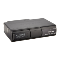
1 Remove the shipping keys.
Three keys are mounted to the DHA-S690's bottom panel
to protect the product during transportation. Be sure to
remove these keys before installing the DHA-S690. So as
not to lose the keys, store them
in
the special plastic
pouch provided with the DHA-S690 and cover the key
holes with the included dust-prevention seals.
Mounting
strap
"'"
Protective
plastic
bag
for
shipping
keys
. i
~LOCkKeyS
• The eject operation cannot be performed
if
the keys are mounted
when the power is turned on. Turn the power off, then renwve the
keys.
2 Install the L-shaped bracket.
1 Determine the position and angle of installation.
2 Referring
to
step
3,
change the position of the springs
according
to
the angle of installation.
3 Install the L-shaped bracket@ according
to
the angle of
installation. Fasten
it
in
place using the double washer
screws (M4x8)
@.
0
0 0
0
0
0 0
0
oe
eo
De
eo
0
8
80
00
00
L-shaped
bracket
holes
• Example of Installation Using Attached L-
shaped bracket.
Vertical
Horizontal
Use
any
pair
of
holes
Use
any
pair
of
holes
e
or
e and fix
wittl
O.eor.andfix
4
screws
(2
screws
x
with
4 screws
both sides).
(2
screws
x
both
sides).
~
~
3 Change the position of the springs.
With this product, the positions of the built-in anti-vibration
springs must be changed according to the angle of
installation. The product will not provide the regular
resistance to vibration
if
the anti-vibration springs are not
in the correct positions or if the left and right springs are
in
different positions.
The anti-vibration springs can
be
placed at one of five
angles.
The springs are set to the "H" angle upon shipment from
the factory.
To
change this angle. follow the instructions
given below.
Remove
the
covers provided at both left and right sides of
the
unit by pressing claws of the covers
in
the direction
shown by the
arrow.
COVER
~
~
2
3
Change the position of the springs
using a finger.
Mount the covers at the left and
right sides
as
they were attached
originally.
38-EN
• Install the unit only at a horizontal
or
vertical angle.
If
the unit is
diagonally installed, malfunction may result.