Maintenance
Electrical contact densimeter threshold in sp ectio n
L51--107EN/01
4/8
06--2003
E ALSTOM
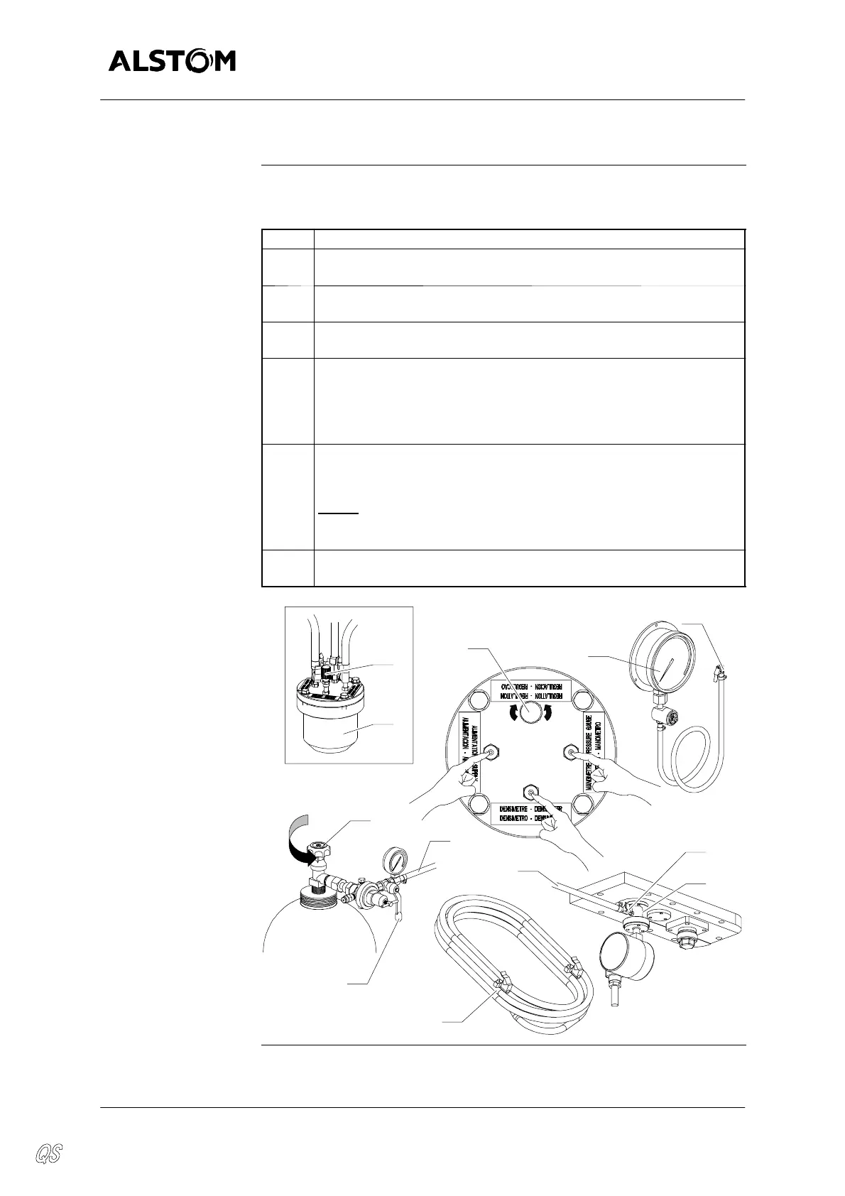
Linking the densimeter on the control tool
Process
The table below gives the process to link the densimeter on the control
tool :
Step Action
1 Check that the “REGULATION” knurl knob (20) of the threshold
inspection tank (4) is in “valve closed” position (unscrewed).
2 Connect the pipe (12) of the gauge (11) on the “PRESSURE
GAUGE” valve of the threshold inspection tank (4).
3 Connect the supplied pipe (6) on the “DENSIMETER” valve of the
threshold inspection tank (4).
4 Briefly open the SF
6
gas bottle tap (21) and the cock (22) of the pres-
sure reducer to eliminate any air inside the pipe (23) (approx. 20 s
at low flow--rate).
Connect thepipe (23) on the “SUPPLY” valve of the threshold inspec-
tion tank (4).
5 Briefly open the SF
6
gas bottle tap (21) and the cock (22) of the pres-
sure reducer to eliminate any air inside the pipe (6) (approx. 20 s at
low flow--rate).
NOTE
: Keep the end of the tube (6) in high position to keep
the SF
6
gas which it contains and to prevent damp air from
entering.
6 Connect the pipe (6) on the valve (24) of the connection valve block
(5).
23
11
5
21
SF
6
6
4
12
20
22
24
6
20
CLOSEOPEN
(leak)