=>?@
Manual operations
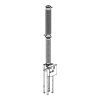
FK 3-1 / FK 3-06 motor-wound spring
operating mechanism
21.5.2003
© ALSTOM
48.020.181E/2
19/26
Manual discharge of closing spring
The operating mechanism has been made ready for manual op-
erations.
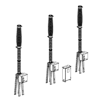
Positions of position indicators
Verify operating state
of circuit breaker and
spring operating
mechanism
Spring position indicator shows
spring charged
Circuit breaker position indicator
shows OPEN, trip spring discharged
Tools required 70.71 Closing latch disabling device
71.15 Closing spring discharging device
71.16 Motor limit switch disabling plate
70.58 Manual release disabling plate 1)
1) Required only for a spring operating mechanism equipped with an un-
dervoltage release but no integral disabling feature
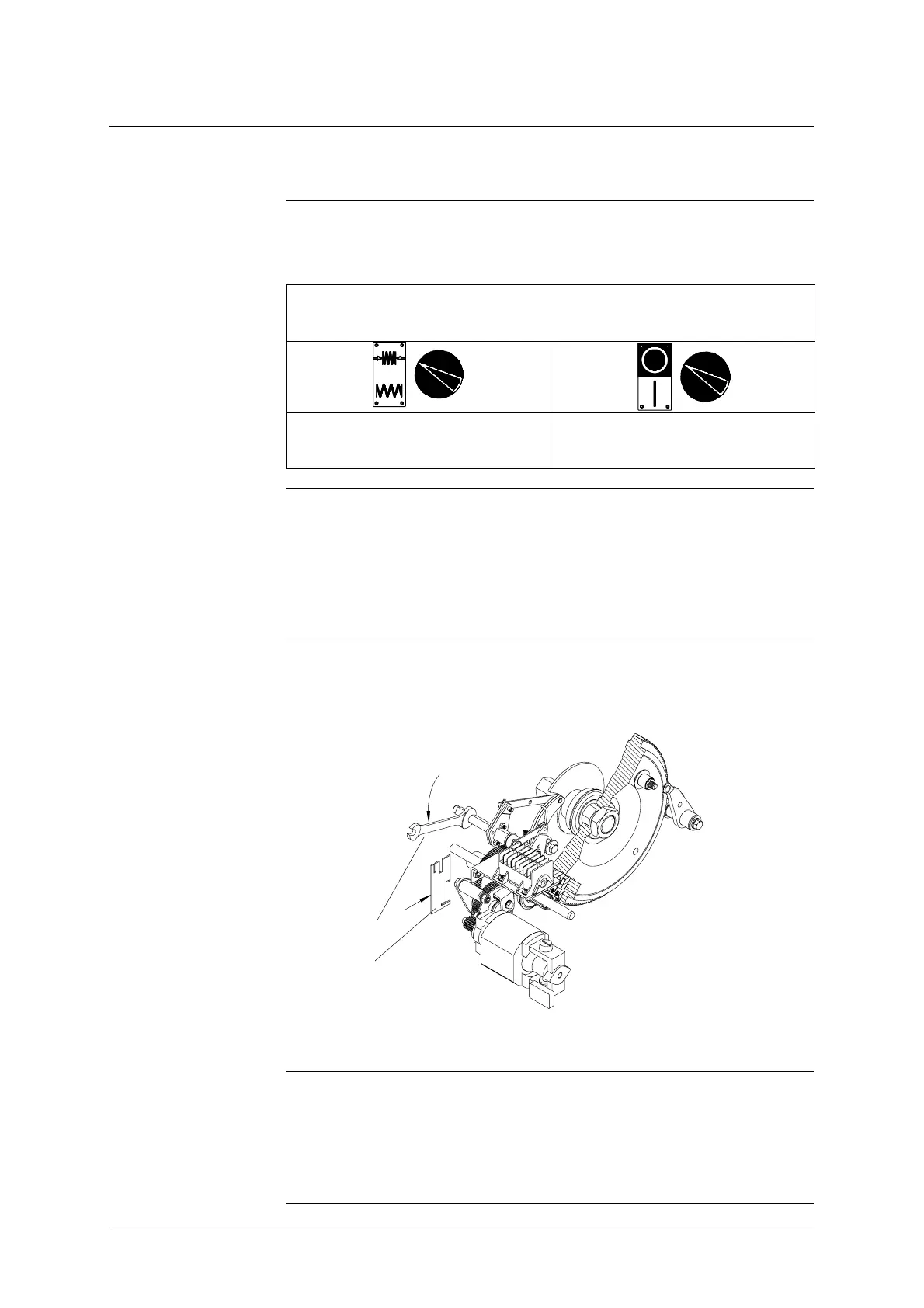
Place motor limit
switch in “closing
spring discharged”
position
• Using open-end wrench 71.12 (S = 12 mm), turn the square shaft of the
spring position indicator counterclockwise.
FK 3-1 shown
71.16 Motor limit switch disabling plate 71.12 Open-end wrench
(S=12)
Block motor limit
switch in “closing
spring discharged”
position
• Using the open-end wrench, turn the shaft until motor limit switch dis-
abling plate 71.16 can be engaged with the motor limit switch bracket
and the axis of the motor limit switch lever as shown in the drawing.
Blocking the switch in this way prevents the auxiliary switch from rotating
back into the starting position.
71.12
71.16
FK 3-1 shown