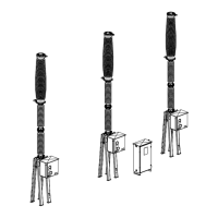
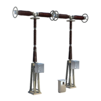
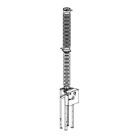
Description and operation
Operating d evice
L14--007EN/01
5/6
07--2003
E ALSTOM
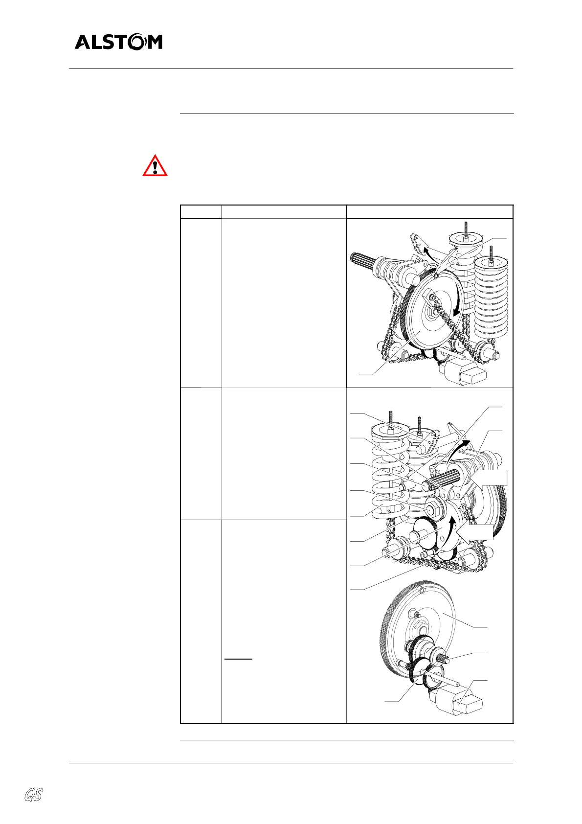
Operating principle
Closing
The table below gives the stages of closing operation :
OPERATION AUTHORIZED ONLY IF THE OPERATING DEVICE IS CON-
NECTED TO THE CIRCUIT BREAKER.
THE CIRCUIT BREAKER MUST NOT BE OPERATED AT A SF
6
PRES-
SURE GAS LOWER THAN THE MINIMAL PRESSURE FOR THE INSULA-
TION p
me
.
Stage
Description Diagram
1 When the closing coil is
stimulated or the manual
closing lever is operated,
the closing latch (14) re-
leases the inertia flywheel
(8).
14
8
2 D The closing shaft (7) ef-
fects a 180° rotation gener-
ated by the loaded closing
spring (9).
D The cam (10) rotates the
main shaft (1) by means of
the lever with roller (11). Af-
ter a 60° rotation, the lever
(5) rests on the opening
latch (6).
7
1
11
6
33
60°
3
5
2bis D Simultaneously, the
opening spring (3) is loaded
by means of the chain (34)
activated by the rotation of
the lever (33).
D A freewheel, installed on
the gear wheel (19), avoids
the reducing gears (13) and
the motor (12) being driven
by the gear wheel of the in-
ertia flywheel (8).
NOTE
: A device pre-
vents all closing opera-
tions if the circuit--breaker
is already in the
“CLOSED” position.
10
180°
12
19
13
9
34
8
Continued on next page.