Description and operation
Operating d evice
L14--007EN/01
3/6
07--2003
E ALSTOM
Auxiliary fittings
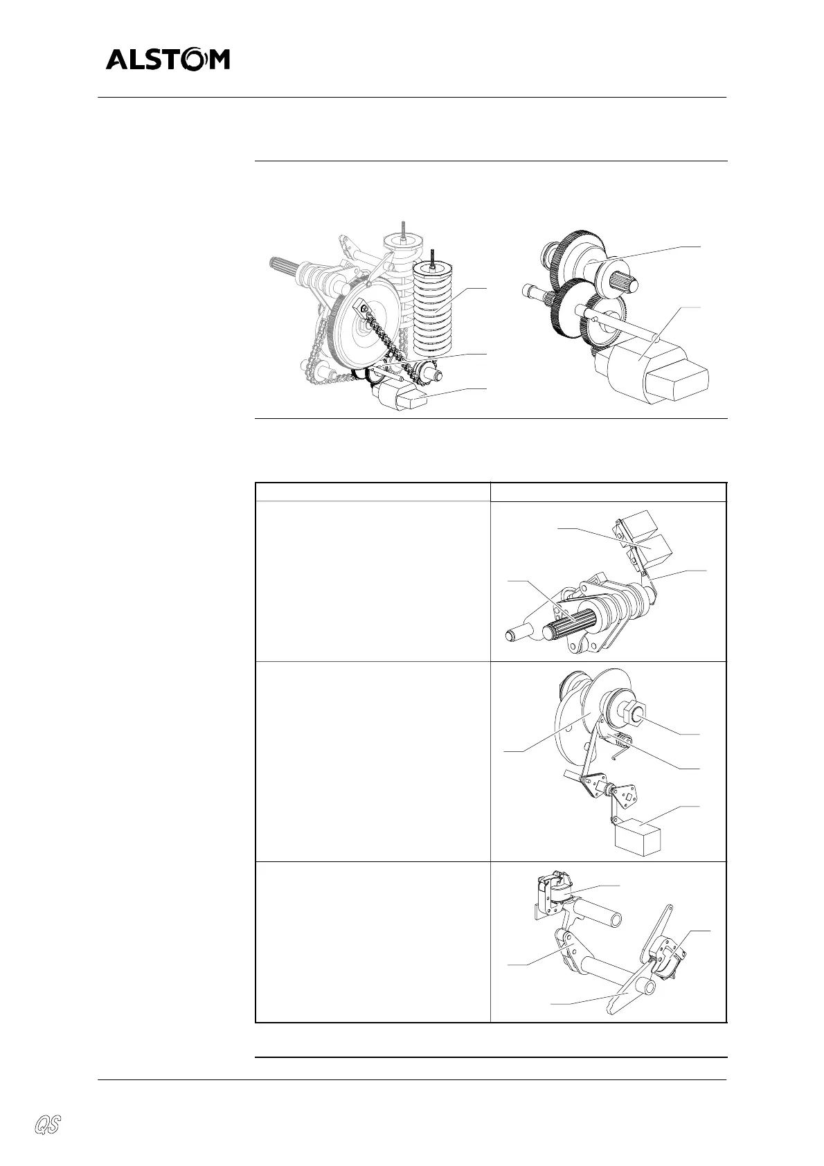
Reloading the closing
spring
The closing spring (9) is loaded by means of the reducing gears (13) and the
motor (12).
9
13
12
13
12
Auxiliary electric
fittings
The table below describes the main parts of the auxiliary electric fittings :
Auxiliary electric fittings Diagram
The alarm contacts (30) are acti-
vatedby a rod anda lever (31), the lat-
ter is activated by the main shaft (1).
30
1
31
The limitswitch of themotor (17) is
activated by the cam (26) and the
lever (35).
The cam (26) is installed on the clos-
ing shaft (7).
26
17
35
7
The closing latch (14) and the open-
ing latch (6) are electrically activated
by coils (22) “Closing” and (27)
“Opening”.
6
27
14
22
Continued on next page.