EAV64301 01/2015 67
Wiring Diagrams
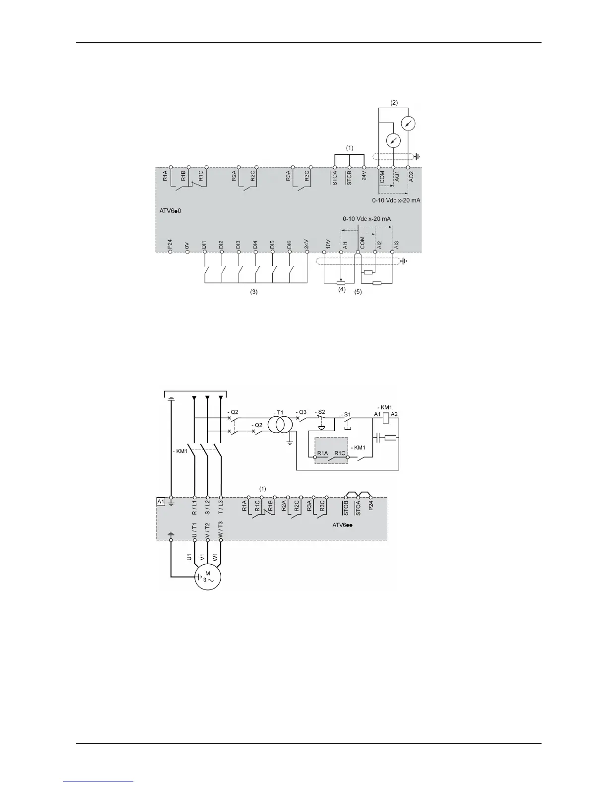
Control Block Wiring Diagram
(1) Safe Torque Off, (2) Analog Output, (3) Digital Input, (4) reference potentiometer (ex. SZ1RV1002), (5)
Analog Input
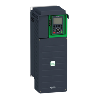
Single or Three-phase Power Supply - Diagram With Line Contactor Without Safety Function STO
Connection diagrams conforming to standards EN 954-1 category 1 and IEC/EN 61508 capacity SIL1,
stopping category 0 in accordance with standard IEC/EN 60204-1.
(1) Use digital output R1 set to operating state Fault to switch Off the product once an error is detected.