86 EAV64301 01/2015
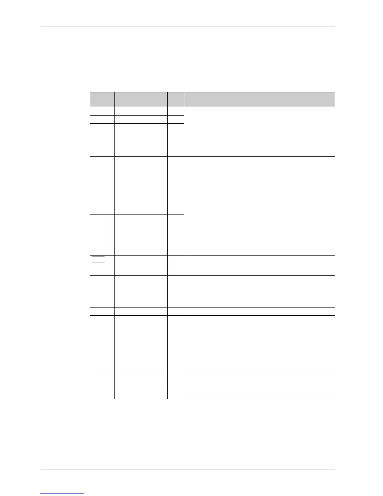
Control Terminals Electrical Data
Characteristics of Terminals
NOTE:
z For a description of the terminal arrangement, refer to Arrangement and Characteristics of Control
Terminals and Communication And I/O Ports (seepage88)
z For factory setting I/O assignment, refer to the Programming Manual.
Terminal Description I/O
Type
Electrical characteristics
R1A NO contact of relay R1 O Output Relay 1
z Minimum switching current: 5 mA for 24 Vdc
z Maximum switching current on resistive load: (cos ϕ = 1): 3 A for
250 Vac and 30 Vdc
z Maximum switching current on inductive load: (cos ϕ = 0.4 and
L/R = 7 ms): 2 A for 250 Vac and 30 Vdc
z Refresh time: 5 ms +/– 0.5 ms
z Service life: 100,000 operations at maximum switching current
R1B NC contact of relay R1 O
R1C Common point contact
of relay R1
O
R2A NO contact of relay R2 O Output Relay 2
z Minimum switching current: 5 mA for 24 Vdc
z Maximum switching current on resistive load: (cos ϕ = 1): 3 A for
250 Vac and 30 Vdc
z Maximum switching current on inductive load: (cos ϕ = 0.4 and
L/R = 7 ms): 2 A for 250 Vac and 30 Vdc
z Refresh time: 5 ms +/– 0.5 ms
z Service life: 100,000 operations at maximum switching power
R2C Common point contact
of relay R2
O
R3A NO contact of relay R3 O Output Relay 3
z Minimum switching current: 5 mA for 24 Vdc
z Maximum switching current on resistive load: (cos ϕ = 1): 3 A for
250 Vac and 30 Vdc
z Maximum switching current on inductive load: (cos ϕ = 0.4 and
L/R = 7 ms): 2 A for 250 Vac and 30 Vdc
z Refresh time: 5 ms +/– 0.5 ms
z Service life: 100,000 operations at maximum switching power
R3C Common point contact
of relay R3
O
STOA
,
STOB
STO inputs I Safety Function STO Inputs
Refer to the Safety Function Manual (EAV64334) available on
www.schneider-electric.com
24V Output power supply for
digital inputs and safety
function STO inputs
O
z +24 Vdc
z Tolerance: minimum 20.4 Vdc, maximum 27 Vdc
z Current: maximum 200 mA for both 24 Vdc terminals
z Terminal protected against overload and short-circuit
z In Sink Ext position, this supply is powered by external PLC supply
COM Analog I/O common I/O 0 V for Analog outputs
AQ1 Analog output O AQ: Analog output software-configurable for voltage or current
z Voltage analog output 0...10 Vdc, minimum. Minimum load
impedance 470 Ω,
z Current analog output X-Y mA by programming X and Y from
0...20 mA, maximum load impedance 500 Ω
z Maximum sampling time: 10 ms ± 1 ms
z Resolution 10 bits
z Accuracy: ± 1% for a temperature variation of 60°C
z Linearity ± 0.2%
AQ2 Analog output O
P24 External input supply I External input supply +24 Vdc
z Tolerance: minimum 19 Vdc, maximum 30 Vdc
z Current: maximum 0.8 A
0V 0 V I/O 0 V for P24