Operating Instructions DC-xx13 and M31xx
961-00060 rev9 10/25
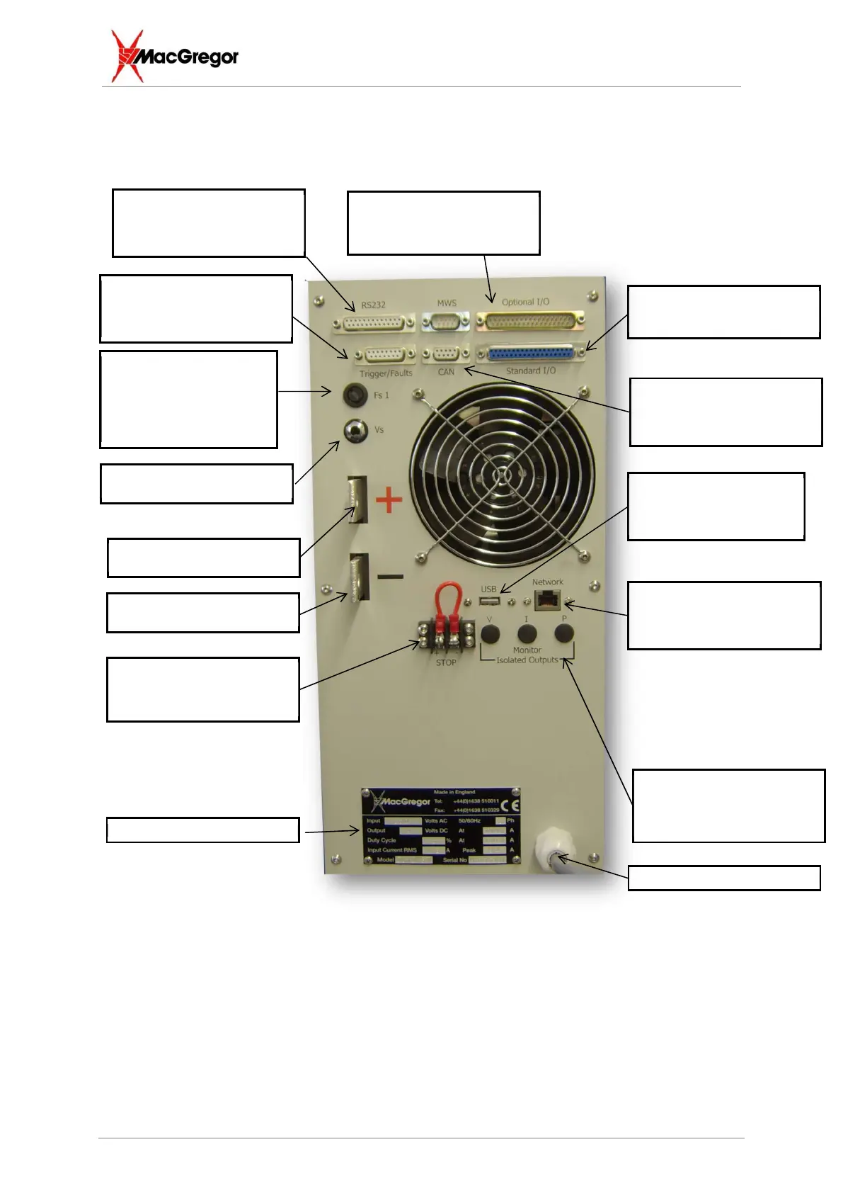
The photo below shows the rear panel connections of a DC6013T or DC1013T
Internal +24V 1amp DC
supply fuse. This is provided
as a protection for the
+24VDC available at the
various D type connectors for
external interfacing
USB port - 0V reference is
taken from the positive output
bar of the machine which is
isolated and floating
Ethernet port - 0V reference is
taken from the positive output bar
of the machine which is isolated
and floating
Isolated RS232
TxD = 2, RxD = 3, GND = 7
Basic digital weld trigger and fault
indication port.
Trigger contact across 1 & 2
Positive Output bar. This is
isolated from earth
Standard optically isolated I/O
PLC Interface for program recalls
and fault indications
Isolated Analogue Channels for
Voltage, Current and Power
0 – 10VDC
Optional optically isolated I/O
PLC Interface for displacement
information and extended I/O
Negative Output bar. This is
isolated from earth
Machine Stop. When this link is
opened, the machine shunt trip
will active, switching off power to
the machine. N.B. Test monthly
MWS Use only.
This is a CAN connection for
MWS peripherals
Voltage sensing jack socket input