Operating Instructions DC-xx13 and M31xx
961-00060 rev9 19/25
5.3 Isolated RS232
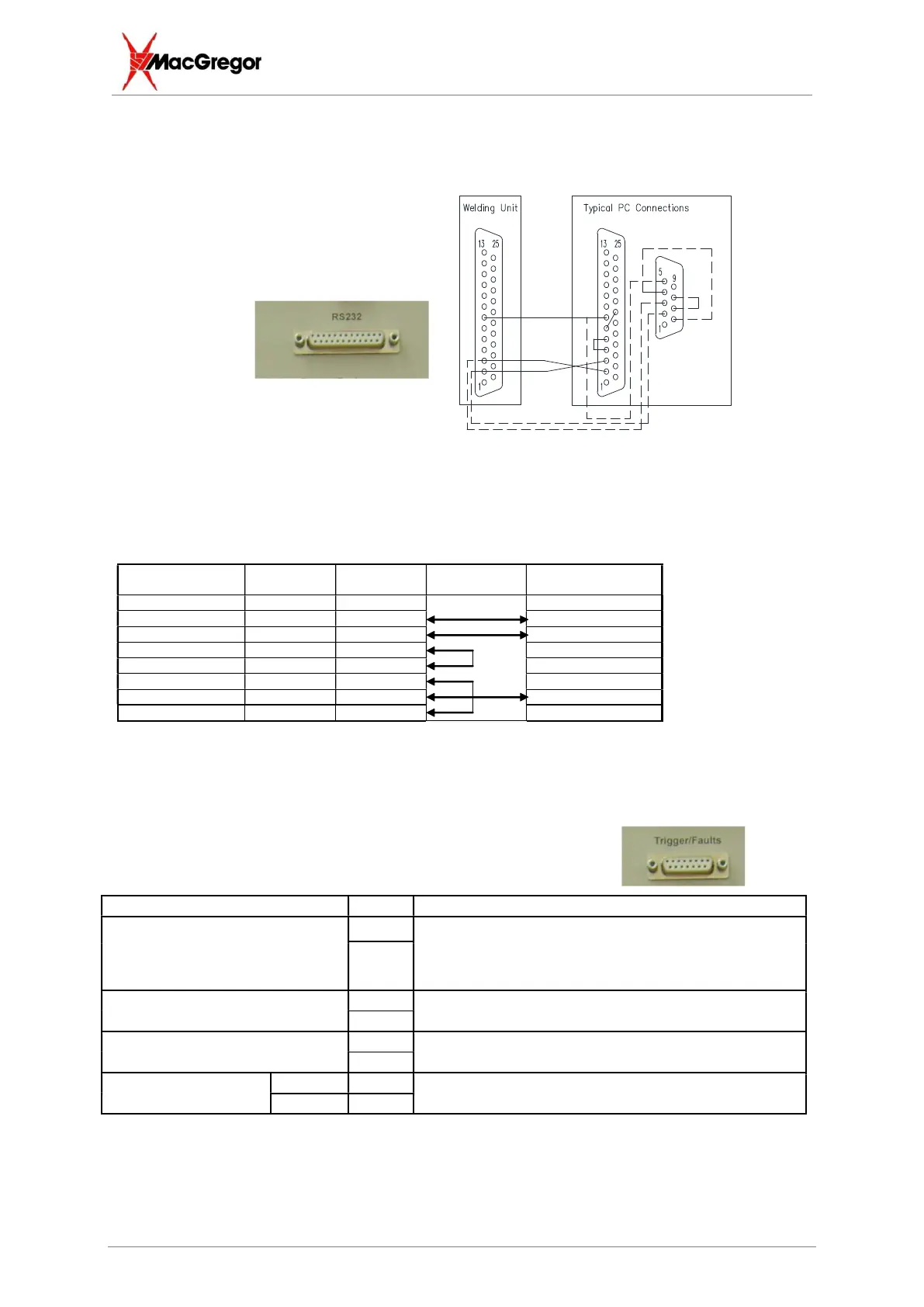
5.4 Connecting a Typical PC Port
A PC uses either a 9-pin D-type serial connector or a 25-pin D-type. The table below shows how to
interface the m3 to either type of PC serial communication port. (Handshake lines CTS,RTS, DSR &
DTR can usually be omitted.
description
comms port
comms port
required
(m3)
Protective ground pin 1 pin 5
Tx pin 2 pin 3 pin 3 (Rx)
Rx pin 3 pin 2 Pin 2 (Tx)
RTS pin 4 pin 7
CTS pin 5 pin 8
DSR pin 6 pin 6
Logical Ground pin 7 pin 5 pin 7 (isolated 0V)
DTR pin 20 pin 4
5.5 15 way Trigger/Fault D type
A 15W D type socket is fitted on many machine variants to provide the following useful signals and
indicators.
Remote weld trigger (of store 0)
by contact closure
1 Pin 1 is hardwired to 0V (pin14) and pin 2 is the
cathode connection for store 0
** NB ** This is NOT isolated from the internal 24v
2
Normally open contacts used to
indicate a fault condition
4 The relay contacts rating is 24V at 0.5A
The contacts close for a Feedback Fault.
5
Remote fault reset by contact
closure
7 Pin 8 is hardwired to +24VDC (pin 15) and pin 7 is the
anode connection for this input
8
Externally available
power supply
0V 14 Protected by fuse Fs2 in the rear panel rated at 1A
anti-surge type T
24VDC 15
The 25 Way D type connector provides
an optically isolated RS232
communications port.
Connections are as follows;
TXD pin 2
RXD pin 3
0V pin 7
.