Operating Instructions DC-xx13 and M31xx
961-00060 rev9 16/25
6 Low Limit Pulse 1 and Low Limit Pulse 2
7 High Limit Pulse 1 and Low Limit Pulse 2
8 High Limit Pulse 1 and High Limit Pulse 2
9 Output Stage Temperature Error
10 24 VDC Error (Missing 24 VDC)
11 Missing Input Phase(s) (Only Active on DC1001P / DC1801P)
12 Missing Voltage Sensing Lead
13 reserved
14 reserved
15 reserved
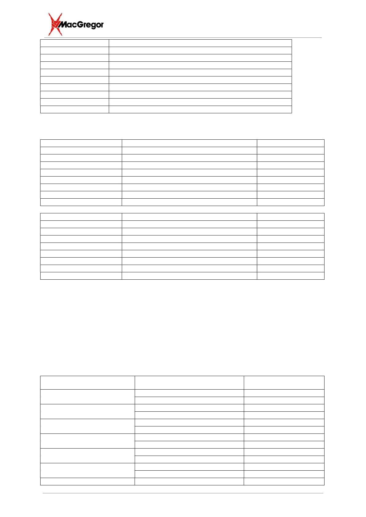
5.1.5 BCD Option Configuration
Standard Output #1 BAD Weld 28, 17
Standard Output #2 Good Weld 10, 35
Standard Output #3 BCD Value 4 29, 36
Standard Output #4 Feedback Fault 11, 13
Standard Output #5 BCD Value 1 12, 15
Standard Output #6 BCD Value 2 31, 32
Standard Output #7 Busy 33, 34
Standard Output #8 Inhibit Status 14, 16
Standard Input #1 Recall Store 0 (display) 21, 27
Standard Input #2 Spare 3, 8
Standard Input #3 Reset (Stop Welder) 1, 26
Standard Input #4 Trigger 22, 7
Standard Input #5 Recall BCD 0 4, 5
Standard Input #6 Recall BCD 1 20, 24
Standard Input #7 Recall BCD 2 2, 6
Standard Input #8 Recall BCD 3 23, 25
Outputs are identical to the default configuration apart from the Good/Bad weld indicators. One of
these is activated after each weld. Inputs are identical to the DS option configuration.
5.2 Optional IO Isolated Interface
The following tables show the expanded outputs and inputs available at the optional extra 37W D type
PLC interface socket.
24V 20mA nominal rating - - Inputs and Outputs ARE fully protected against short circuit and overload.
Operation of the outputs and inputs is identical to the standard IO.
5.2.1 Optional Outputs
Output Description D-type Pin Number
Optional Output #1
Collector 1
Emitter 20
Optional Output #2
Collector 2
Emitter 21
Optional Output #3
Collector 3
Emitter 22
Optional Output #4
Collector 4
Emitter 23
Optional Output #5
Collector 5
Emitter 24
Optional Output #6
Collector 6
Emitter 25
Optional Output #7 Collector 7