Operating Instructions DC-xx13 and M31xx
961-00060 rev9 17/25
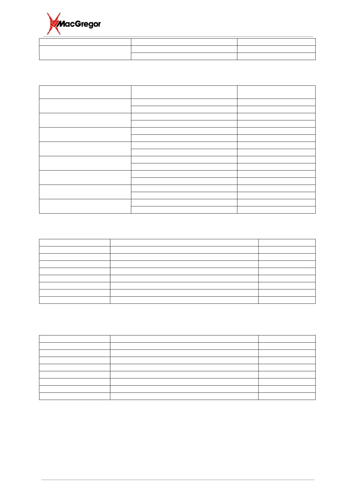
Emitter 26
Optional Output #8
Collector 8
Emitter 27
5.2.2 Optional Inputs
Input Description D-type Pin Number
Optional Input #1
Anode 9
Cathode 13
Optional Input #2
Anode 28
Cathode 32
Optional Input #3
Anode 10
Cathode 14
Optional Input #4
Anode 29
Cathode 33
Optional Input #5
Anode 11
Cathode 15
Optional Input #6
Anode 30
Cathode 34
Optional Input #7
Anode 12
Cathode 16
Optional Input #8
Anode 31
Cathode 35
5.2.3 Default Configuration
Optional Output #1 Spare 1, 20
Optional Output #2 Spare 2, 21
Optional Output #3 Remote Inhibit 3, 22
Optional Output #4 Displacement Max Fault 4, 23
Optional Output #5 Displacement Min Fault 5, 24
Optional Output #6 Displacement Condition Fault 6, 25
Optional Output #7 Displacement Oversize Fault (pre-weld) 7, 26
Optional Output #8 Displacement Undersize Fault (pre-weld) 8, 27
Note that all fault outputs turn OFF the opto-transistor.
Optional Input #1 New Electrode Input 1 9, 13
Optional Input #2 Reset HW 28, 32
Optional Input #3 Toggle Inhibit 10, 14
Optional Input #4 New Electrode Input 2 29, 33
Optional Input #5 New Electrode Input 3 11, 15
Optional Input #6 New Electrode Input 4 30, 34
Optional Input #7 New Electrode Input 5 12, 16
Optional Input #8 New Electrode Input 6 31, 35