Operating Instructions DC-xx13 and M31xx
961-00060 rev9 15/25
Standard Input #1 Recall Store 0 (display) 21, 27
Standard Input #2 Recall Store 1 3, 8
Standard Input #3 Recall Store 2 1, 26
Standard Input #4 Recall Store 3 22, 7
Standard Input #5 Recall Store 4 4, 5
Standard Input #6 Recall Store 5 20, 24
Standard Input #7 Recall Store 6 2, 6
Standard Input #8 Recall Store 7 23, 25
5.1.4 DS Option Configuration
Standard Output #1 Fault BCD Code 0 28, 17
Standard Output #2 Inhibit Status 10, 35
Standard Output #3 Fault BCD Code 3 29, 36
Standard Output #4 Feedback Fault 11, 13
Standard Output #5 Fault BCD Code 1 12, 15
Standard Output #6 Fault BCD Code 2 31, 32
Standard Output #7 Busy 33, 34
Standard Output #8 Spare 14, 16
Standard Input #1 Recall Store 0 (display) 21, 27
Standard Input #2 Spare 3, 8
Standard Input #3 Reset (Stop Welder) 1, 26
Standard Input #4 Trigger 22, 7
Standard Input #5 Recall BCD 0 4, 5
Standard Input #6 Recall BCD 1 20, 24
Standard Input #7 Recall BCD 2 2, 6
Standard Input #8 Recall BCD 3 23, 25
The following specifies the functionality for the DS Isolated Interface:
The software has been enhanced to provide up to 15 error codes which are output via the optically
isolated output pins in a BCD code format. These error codes are held at the output until the RESET
signal is applied. The Fault Hardware Interrupt signal is also cleared in this fashion using the RESET
signal.
The fault conditions are summarised below.
0 No fault
1 Pulse 1 High Limit
2 Pulse 1 Low Limit
3 Pulse 2 High Limit
4 Pulse 2 Low Limit
5 Low Limit Pulse 1 and High Limit Pulse 2
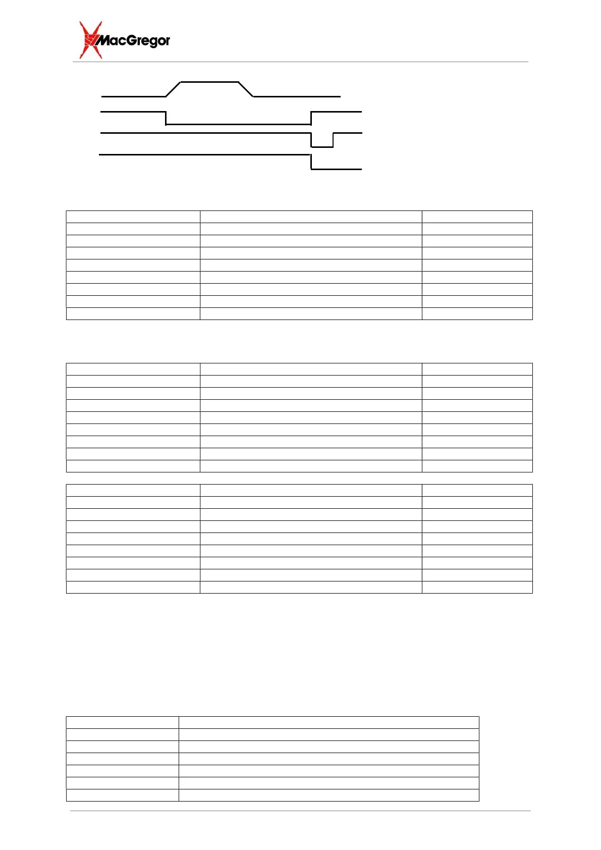
Weld Pulse
Busy Signal - Active
during weld + 30mS
Hi/Low Fault – User
Hardware/Feedback Fault