Operating Instructions DC-xx13 and M31xx
961-00060 rev9 13/25
5 Rear Panel Connections
5.1 Standard IO Isolated Interface
The following tables show the standard outputs and inputs available at the 37W D type PLC interface
socket.
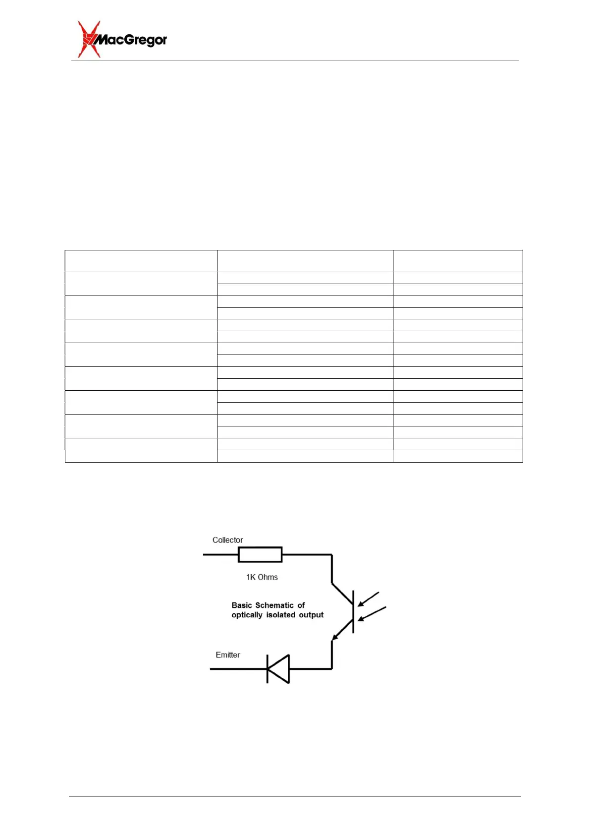
24V 20mA nominal rating - - Inputs and Outputs ARE fully protected against short circuit and overload.
Also shown are the available initial IO configurations. Note that it is now possible to modify these
configurations if desired. This includes changing whether outputs are asserted high/low on activation
and on whether inputs are triggered on high-low or low-high transitions. For more details, see the
software manual IO Configuration section.
5.1.1 Standard Outputs
Output Description D-type Pin Number
Standard Output #1
Collector 28
Emitter 17
Standard Output #2
Collector 10
Emitter 35
Standard Output #3
Collector 29
Emitter 36
Standard Output #4
Collector 11
Emitter 13
Standard Output #5
Collector 12
Emitter 15
Standard Output #6
Collector 31
Emitter 32
Standard Output #7
Collector 33
Emitter 34
Standard Output #8
Collector 14
Emitter 16
Typically, the collector connection is pulled up to +24VDC (obtained on pin 37) and is used as the
input to a PLC, while the emitter is connected to 0V(+24RTN), obtained on pin 19.
Passing current activates the output.