Operating Instructions DC-xx13 and M31xx
961-00060 rev9 14/25
5.1.2 Standard Inputs
Input Description D-type Pin Number
Standard Input #1
Anode 21
Cathode 27
Standard Input #2
Anode 3
Cathode 8
Standard Input #3
Anode 1
Cathode 26
Standard Input #4
Anode 22
Cathode 7
Standard Input #5
Anode 4
Cathode 5
Standard Input #6
Anode 20
Cathode 24
Standard Input #7
Anode 2
Cathode 6
Standard Input #8
Anode 23
Cathode 25
Externally available 24V
+24VDC 37
0V (24 RTN) 19
Remote Reset
Anode (must be volt-free) 18*
Cathode (internally hardwired to 0V
pin 19)
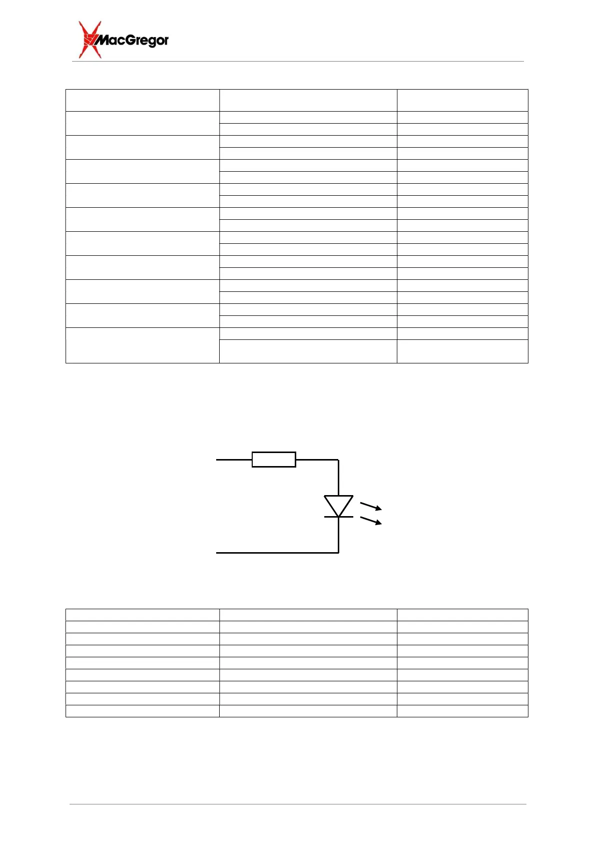
Typically, the anode is connected directly to +24VDC (obtained on pin 37) while the cathode is
connected via a PLC or switch to 0V(+24RTN), obtained on pin 19.
Passing current activates the input.
5.1.3 Default Configuration
Standard Output #1 Fault High Limit 28, 17
Standard Output #2 Fault Low Limit 10, 35
Standard Output #3 BCD Value 4 29, 36
Standard Output #4 Feedback Fault 11, 13
Standard Output #5 BCD Value 1 12, 15
Standard Output #6 BCD Value 2 31, 32
Standard Output #7 Busy 33, 34
Standard Output #8 Inhibit Status 14, 16
The BCD outputs are used to select channels when configured for electrical distribution with
MacGregor distribution units. These outputs turn ON the opto transistor when selected. All fault
outputs and the busy output turn OFF the opto-transistor when active.
A typical timing diagram of selected outputs might look as follows:
Basic Schematic of
optically isolated input