11
Converting 3-Wire to 4-Wire Power Cord
1. Remove rear wire cover.
2. Remove bottom strain relief screw and retain for
further use.
3. Remove screw/hex nuts from terminal block and
retain for further use.
4. Remove all 3-wire or cable leads from the terminal
block and proceed to remove the power cord from the
range by pulling in a downward motion so the cord is
removed from strain relief.
5. To install the 4-wire cord, please follow step 3
through step 9 of
Installing 4-Wire Power Cord
section.
Duct Requirements
• Duct should be 6-inch round metal ducting. Island or
peninsula installations may require 3
1
/4 X 10 inch duct.
• To ensure proper ventilation, duct work must not
exceed 60 equivalent feet.
• Curved fittings should not account for more than 50% of
duct length.
• Flexible duct is not recommended because of irregular
interior surface. If flexible duct is to be used, one foot is
equal to 2 feet of metal duct. NEVER USE PLASTIC
TYPE DRYER DUCTING.
• Do not vent into an attic or crawl space. Vent range
outside.
• Flexible duct elbows are equal to twice as many feet
as smooth metal elbows.
• Never install two elbow fittings next to each other. Two
elbows installed together create a poor vent path and
insufficient ventilation.
• Seal all duct joints tightly using duct tape. Openings
left in ducting allow smoke and odor to escape inside
house.
• For best performance, do not use more than three 90°
elbows.
• 6-inch transition duct provided must be mechanically
secured to exhaust blower outlet. Secure transition
duct using two screws provided.
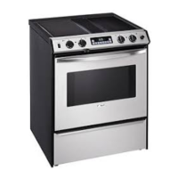
Wires from power cord
A
A
B
Wires from range
(Number of wires on each terminal can vary)
A—240 or 208 power lead terminal (Connect black or
red insulated wire and secure with brass nut.)
B—Neutral terminal (Connect insulated white insulated
wire and secure with brass nut.)
Figure 13
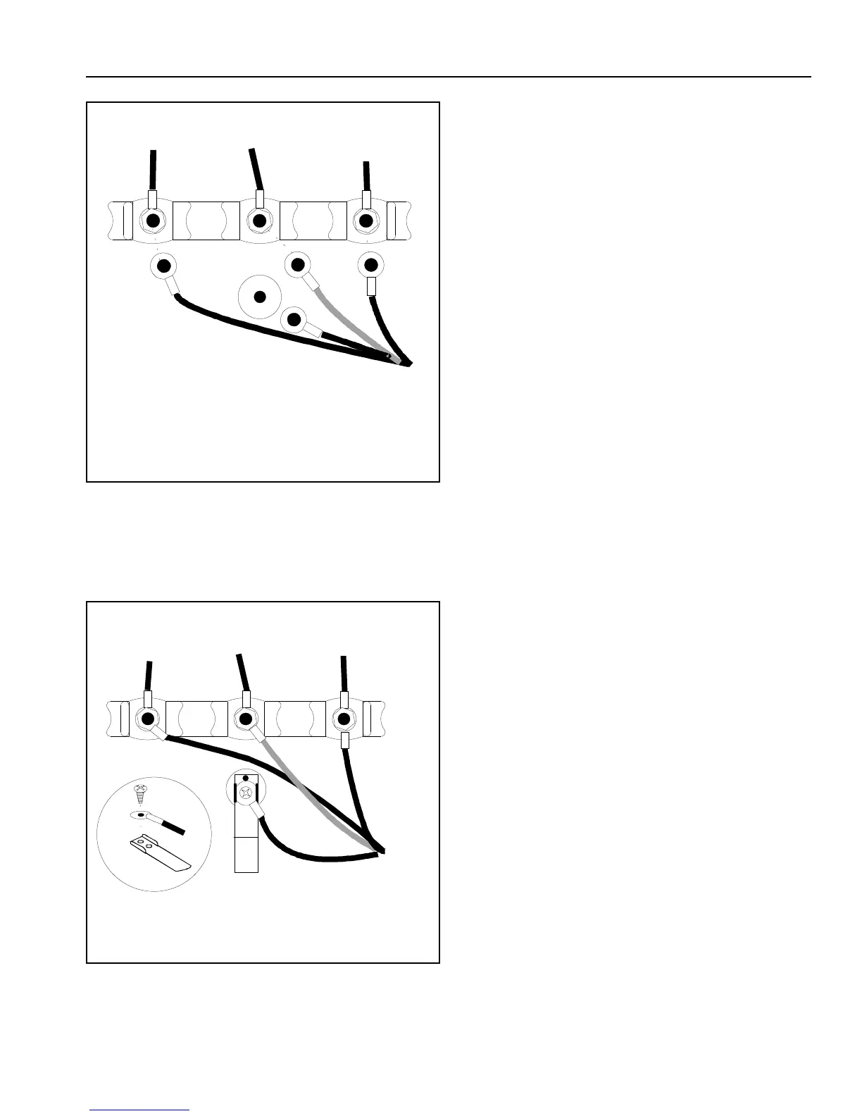
8. See Figure 14. Position grounding strap down and
away from terminal block. Attach green or bare wire
and grounding strap to back of range using green
ground screw previously removed in step 3.
Wires from power cord
A
Wires from range
(Number of wires on each terminal can var
)
A—Ground screw (Connect green insulated wire and
secure with screw.)
Figure 14
9. Firmly tighten all connections to ensure proper
electrical connection.
10. Place screw through strain relief, tighten, and replace
rear wire cover.
 Loading...