8
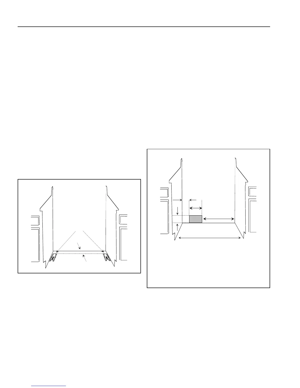
Anti-tip Bracket Installation
See Figure 7. To reduce risk of range tipping, secure
range with a properly installed anti-tip bracket.
1. Measure (A) from back wall on right and left side of
cabinet cutout. Mark measurements on floor and
draw a straight line connecting marks.
• Measure 3
1
/2 inches when installed with
backsplash. See Figure 1.
• Measure 1
3
/4 inches when installed without
backsplash. See Figure 2.
• Drop vertical line from back of cutout and measure
1
1
/2 inches when installed in island. See Figure 3.
2. Position anti-tip bracket.
• If range is installed beside cabinet(s), place anti-tip
bracket with back edge on line drawn on floor and
side of bracket against cabinet.
• If range is not installed beside cabinet(s), position
range where it will be installed. Draw a line along
side of range on floor from front to back. Remove
range. Place anti-tip bracket with back edge over
line drawn from back wall and side of bracket over
line drawn along side of range on floor.
• Anti-tip bracket can be installed on either right or
left side.
A
or
Figure 7
3. Mark 2 hole locations in anti-tip bracket.
4. Drill 2 holes.
• If drilling into wood, use a
3
/32-inch drill bit.
• If drilling into concrete, use a
3
/16-inch masonry drill
bit and insert plastic anchors.
5. Secure bracket to floor using screws supplied. Slide
range into position.
6. Remove range storage drawer or panel and confirm
anti-tip bracket is engaged with range leveling leg.
• See “Removing Storage Drawer” or “Removing
Panel” section.
Line Voltage Requirements
Line voltage must not exceed rated voltage. See rating plate
attached to range for kilowatt rating. Line voltage less than
rated voltage will result in slow heating. Wiring system must
conform to Underwriters Laboratories, Inc. standards and
National Electrical Code. Installation must conform to all
local, municipal and state building codes, and local utility
regulations. Range must be connected only to a supply
circuit as specified on rating plate wiring diagram of range.
This range requires 3 wires, 120/240 Volts, 60 Hertz A.C.
House wiring and fusing must comply with local wiring
codes. If no codes apply, wire according to National
Electrical Codes.
Power Supply Location
See Figure 8. Shaded area show range clearance for
electrical connection.
A
B
C
D
E
A—3
1
/8 inches
B—12
1
/4 inches
C—14
3
/4 inches
D—30
1
/8 inches minimum
E—9
1
/2
Figure 8
 Loading...