27
EN
• Insert the red connector lead (N) into the
positive input jack (K).
• Ω should light up on the display (A).
• Place the test probes (N) across the circuit or
part under test.
• The stabilized value on the display (A) is read as
the actual reading.
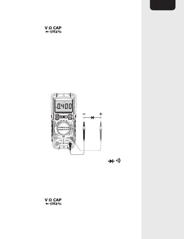
Diode test
• Set the function switch (E) to the Ω CAP
position.
• Insert the black connector lead (N) into the
negative COM input jack (L)
• Insert the red connector lead (N) into the
positive input jack (K).