4
2 Installation instructions.
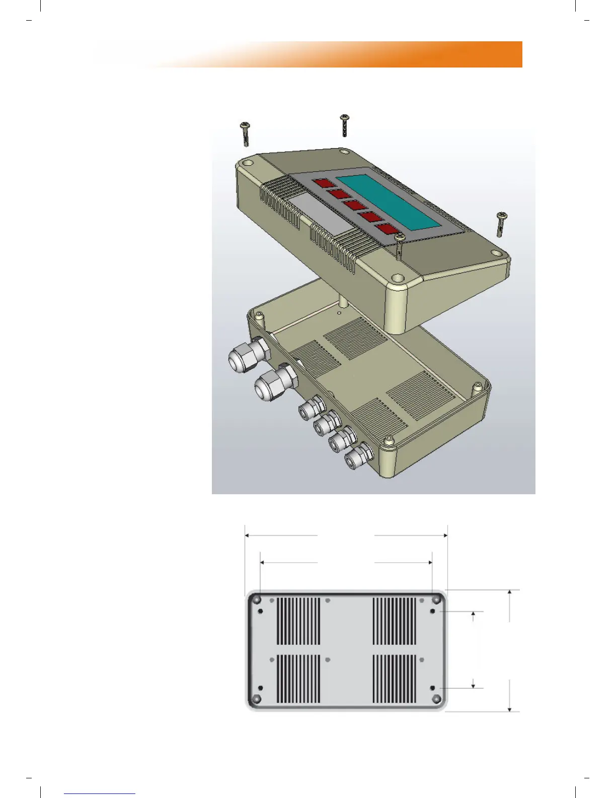
2.1 Mounting the Control Assembly
The housing consists of a
two part plastic moulding
held together by four
screws.
• Remove the screws.
• Carefully lift the lid and
unplug the ribbon cable
from the power PCB
assembly situated in the
bottom of the case.
• A drilling template is provided to
enable the controller assembly to
be securely fixed to a solid
surface.
• It is recommended that the
controller is installed no
less than 5ft above the
floor level.
• The lid with display and
connecting ribbon cable
can be rotated through
180° therefore allowing the
controller to be positioned with
the wire entry to the bottom or the top
depending on the cable routing.
• Do not mount the controller on an
excessively warm or cold surface or where it
could be affected by direct sunlight or other
heat/cool sources.
• The mounting surface
should be non-conducting or
grounded and should
prevent access to the rear of
the
control.
Note: The recommended minimum
mounting height only applies when
the internal sensor is used.
8 13/16”
7 7/8”
3 5/32”
5”