6
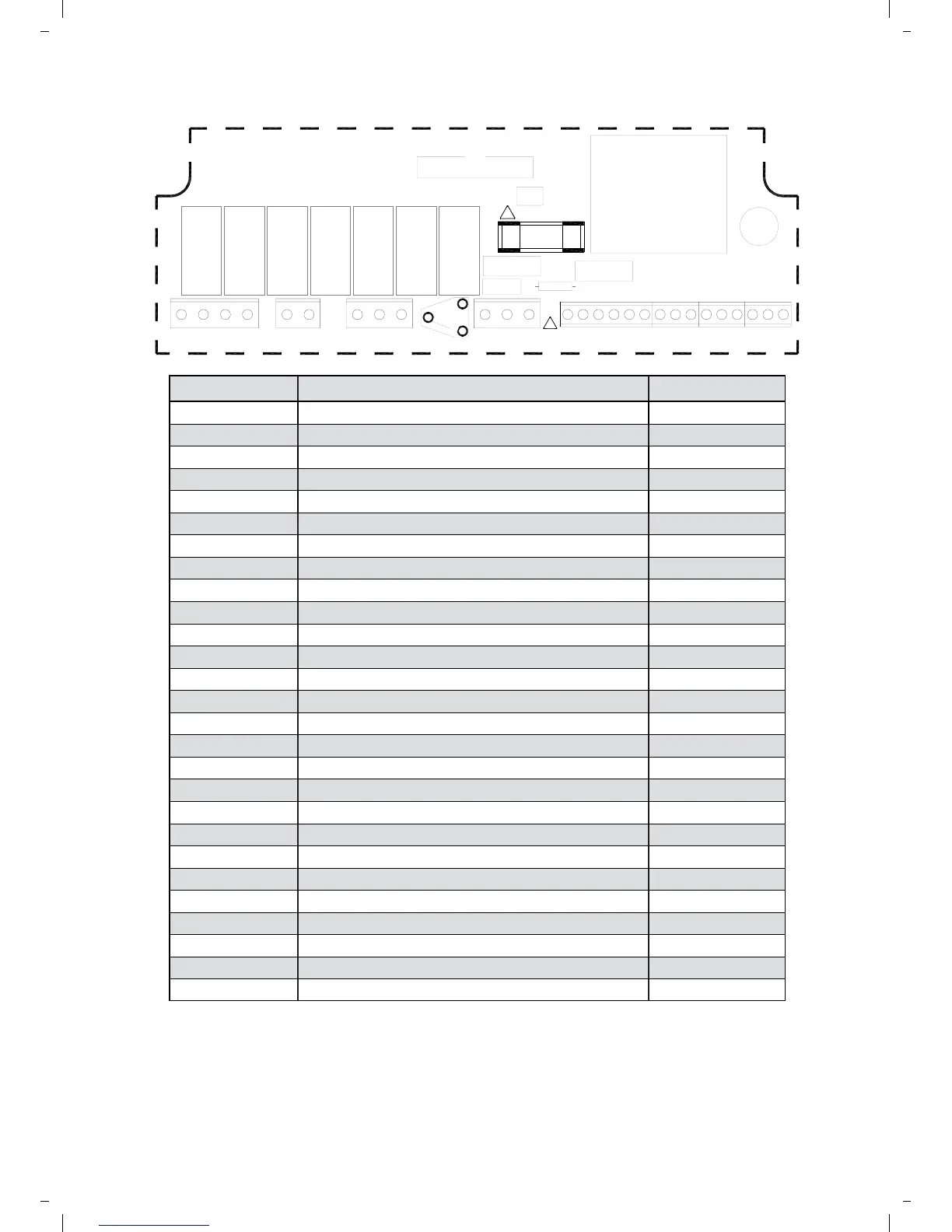
Terminal No. Connection Wire capacity
41
Vent 1 relay input (¾ Hp/low fan) 12 Awg
40
Vent 1 relay output (¾ Hp/low fan) 12 Awg
7
Heat 2 relay input (2 stage) 12 Awg
8
Heat 2 relay output (2 stage) 12 Awg
9
Burner reset output 12 Awg
25
Vent 3 relay output (damper) 12 Awg
14
Vent 2 relay output (high fan) 12 Awg
5
Time relay output 12 Awg
6
Heat 1 relay output (1 stage) 12 Awg
1/L
Live supply input 12 Awg
2/N
Neutral supply input 12 Awg
10
Flame failure input 12 Awg
S/R0
Remote room temperature sensor ‘A’ 14 Awg
S/R1
Remote room temperature sensor ‘B’ 14 Awg
D0
Remote duct temperature sensor ‘A’ 14 Awg
D1
Remote duct temperature sensor ‘B’ 14 Awg
O0
Outside air temperature sensor ‘A’ 14 Awg
O1
Outside air temperature sensor ‘B’ 14 Awg
B1
Remote on input (BMS ON input) 14 Awg
B0
Remote common (output to BMS) 14 Awg
B2
Remote frost input (door interlock) 14 Awg
C2
Comms connection ‘A’ input/output (Networking) 14 Awg
C0
Comms connection ‘GND’ output (Networking) 14 Awg
C1
Comms connection ‘B’ input/output (Networking) 14 Awg
66
Channel 1, 0~10V output (GM44) 14 Awg
64
Channel 1 and 2 common output 14 Awg
20
Channel 2, 0~10V output (damper 14 Awg
2.3 SC3MZ WIRING CONNECTIONS
A terminal block is supplied to enable multiple
connections to B0/B2 as detailed in product
wiring connections. 0-10V outputs and remote
switch inputs should be connected by 18Awg
cable of maximum length 325ft. The remote
temperature sensor may be placed at a
distance of up to 325ft (maximum) from the
control unit, using shielded 18Awg cable to
improve noise rejection. Connect the shield to
terminal B0. Master-slave communication is by
shielded twisted pair cable, RS 485 compatible,
such as Belden 9841 (or Equiv). Maximum
overall system length is 1650ft. Connect shield to
B0 and C0. All sensor and signal wiring should
be kept separate from mains wiring to minimise
noise pick-up.
NEUT
LIVE
1/L 2/N 10
S/R0S/R1D0 D1 O0 O1 B1 B0 B2 C2 C0 C1 66 64 20
41407 8 925 145 6
!
! FUSE RATING
T