1. Important information
This is a reference manual for Ambu® aView™ 2 Advance, item number 405011000, software version 1.0.0.
The reference manual may be updated without further notice. The latest version of the reference manual is available
online at www. ambu.com.
In this reference manual, the term displaying unit refers to aView 2 Advance. Please be aware that this manual does not
explain or discuss clinical procedures. The reference manual describes only information and functions related to the
operation of the aView 2 Advance.
Before operating the displaying unit, please read the Instruction for Use (IFU) delivered with your aView 2 Advance or
download at www.ambu.com.
For specific information about specifications of aView 2 Advance and troubleshooting, please consult the IFU.
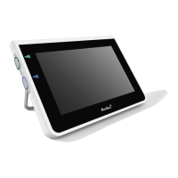
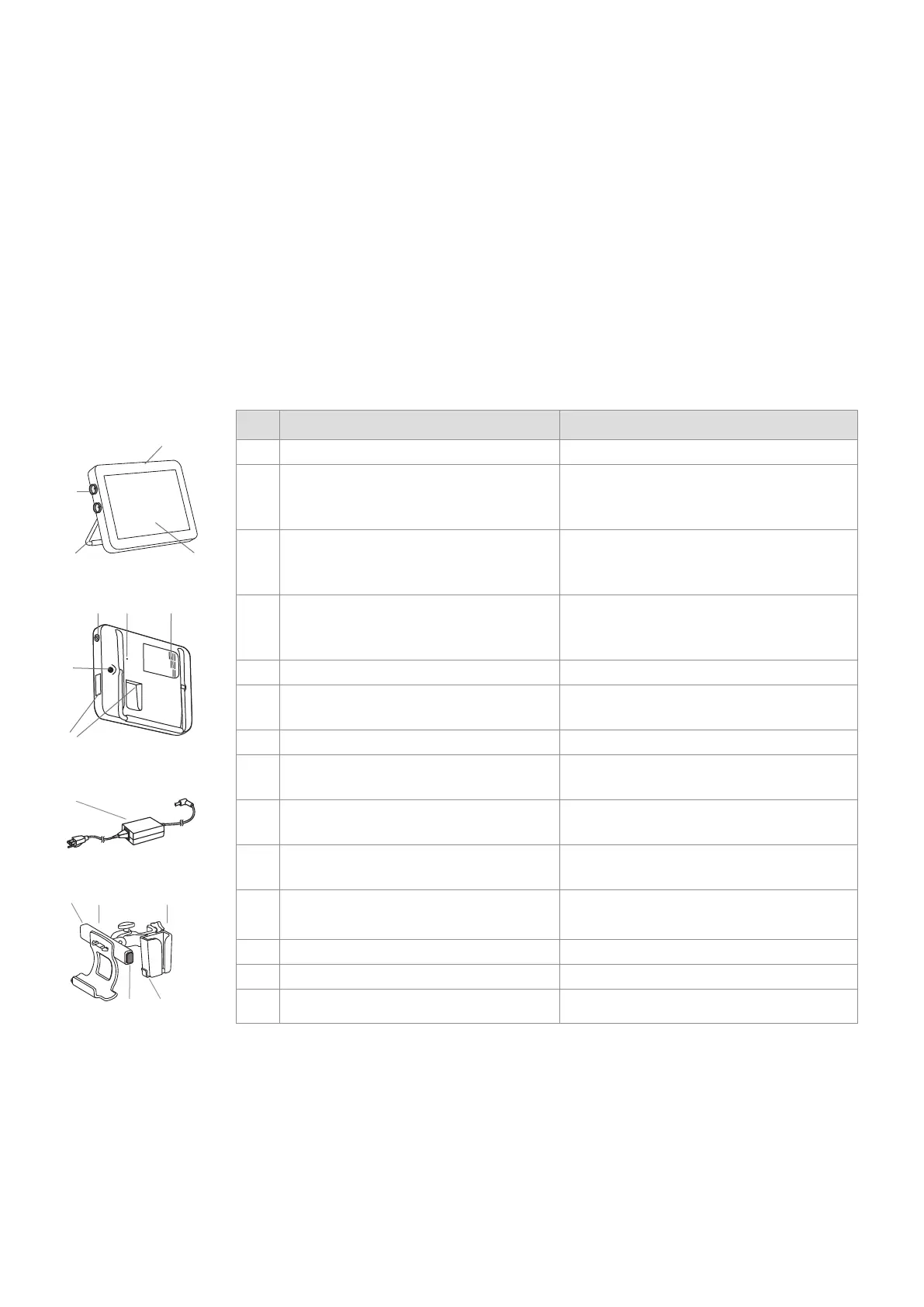
2. Device overview
The displaying unit consists of the parts listed below
No. Part Function
1 Casing -
2 LCD Touch Screen Displays the image from the Ambu
visualization device and the graphical user
interface.
3 Stand Use the stand to place the displaying unit
on a solid surface and to carry the
displaying unit while turned OFF.
4 Connector ports
for Ambu®
visualization devices
Match and align colours and arrows on
device plug and the connector port.
5 Power button Push button for power ON and OFF.
6 Hardware reset button Reset the displaying unit hardware without
impacting stored data.
7 Ventilation holes Cools hardware during use
8 Power inlet Power inlet for charging the displaying unit.
9 Input/output connections* USB, HDMI, SDI, LAN
*Wi-Fi available.
10 Power supply Powers the displaying unit.
Power cord with country-specific plug.
11 Bracket Secures the displaying unit to e.g. an IV
pole.
12 Power supply bracket Secures the placement of the power supply.
13 Release buttons Releases displaying unit from the bracket.
14 Hook Storage of visualization device pouches.
4
1
3 2
5 6 7
10
11 12
13
13
14
4
 Loading...