Installation
Page 3-11
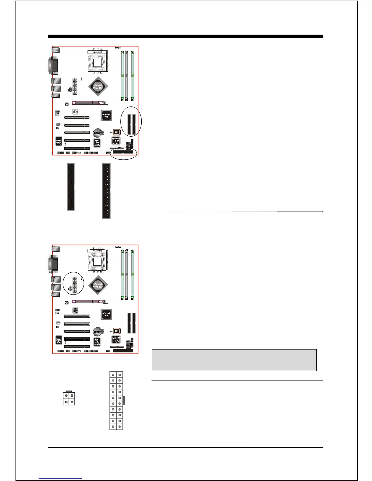
FDD: Floppy Controller Connector
This mainboard is equipped with a floppy disk drive
connector for connecting up to 2 floppy disk drives.
IDE1/IDE2: Ultra DMA-66/100/133 Primary/Secondary
IDE Connector
This mainboard is equipped with 2 IDE disk connec-
tors for connecting up to 4 ATA-133 IDE drives. It
supports PIO and DMA mode operations for
maximum data transfer rate of 133Mbps per channel.
PW1
PW12
PW1: 20-pin ATX Power Connector
PW12: 4-pin ATX12V Power Connector
The mainboard is equipped with a standard 20-pin
ATX main power connector and a 4-pin +12V
power connector for connecting an ATX12V
power supply. The plugs of the power cables are
designed to fit in only one orientation. Find the
proper orientation then insert the plugs into the
connectors until they fit in place.
Caution:
Be sure that the PW1 and PW12 Power Connector must be used
simultaneously or else boot-up may not be possible.
40 39
2
1
IDE1/IDE2
34 33
2
1
FDD
When use two IDE drives, one must be set to Master
mode and the other one to Slave mode. Refer to your
disk drive users manual for information about select-
ing the proper drive switch settings.
The board requires a minimum of 250 Watt power
supply to operate. Your system configuration
(amount of memory, add-in cards, peripherals, etc.)
may exceed the minimum power requirement but to
ensure that adequate power is provided, use a 300
Watt (or greater) power supply.
!
-12V3.3V
Ground+5V
PS-ON+5V
-5VPW-OK
+5V5VSB
+5V+12V
+12V+12V
"
3.3V3.3V
GroundGround
GroundGround
GroundGround
GroundGround
PW1
PW12
IDE1 IDE2
FDD