ALS-600PS Power Supply Board
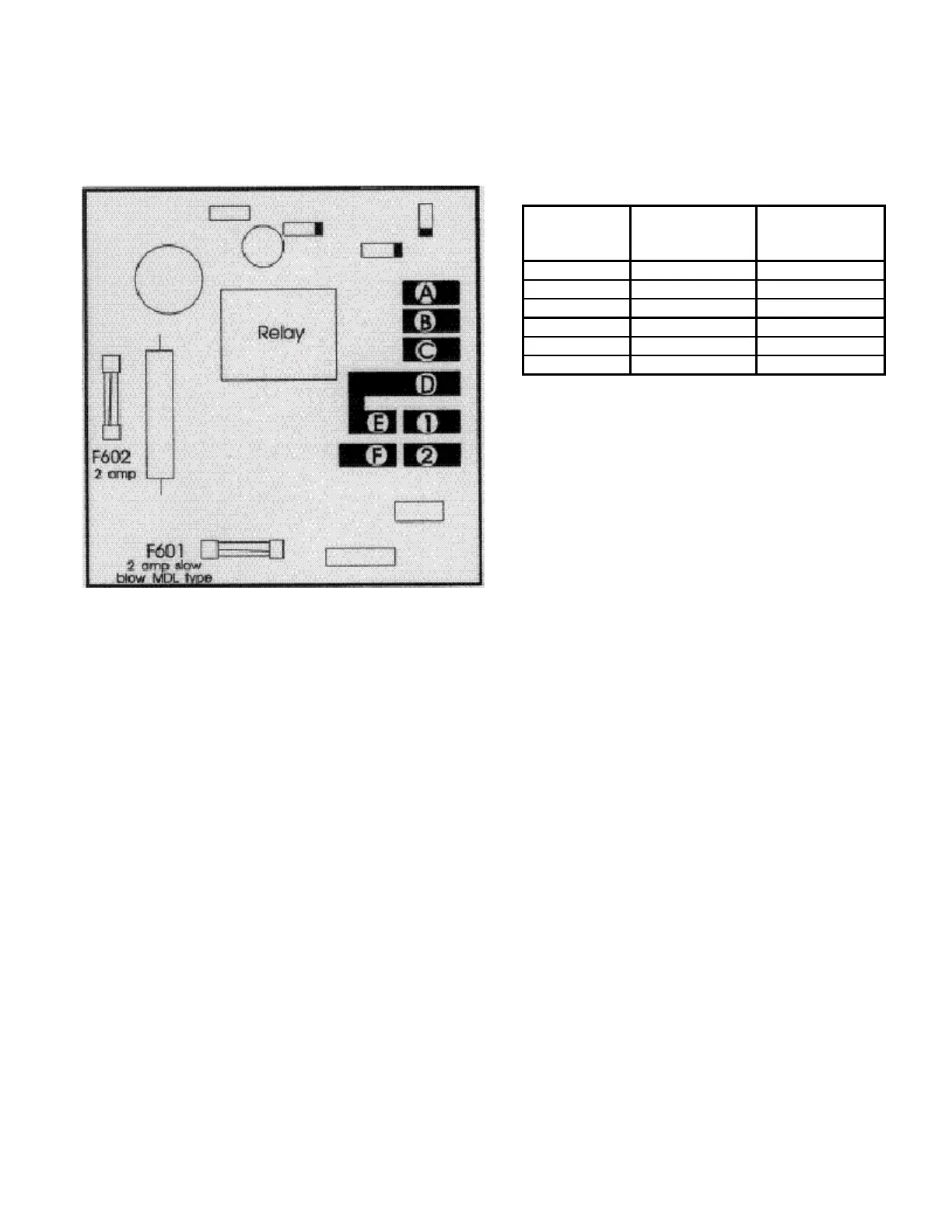
Jumper Pad Diagram
For the following line voltages
jumper the correct pads.
AC LINE
VOLTAGE
RANGE PRIMARY BUCK BOOST
95-110 A TO B C TO D E TO 2 F TO 1
105-120 A TO B C TO D E TO F
115-130 A TO B C TO D E TO 1 F TO 2
200-220 B TO C E TO 2 F TO 1
210-230 B TO C E TO F
220-240 B TO C E TO 1 F TO 2
High Voltage Section
The high voltage section of the ALS-600PS uses a full wave bridge rectifier. DC filtering
is accomplished with a large swinging choke (T1) and a high quality computer grade
capacitor (C5). A pair of 100 ohm resistors (R5,6) absorb enough bleeder current to
prevent the output voltage from soaring under low load currents. The output voltage and
current of this section are monitored by a illuminated dual needle meter (M2a/2b).
Primary Circuit
10 ohm resistor (R602) limits the line current during the filter capacitor charge time to
lower the stress on the power supply components. When the 14 volt control line
approaches full voltage relay (RLY601) bypasses the 10 ohm resistor (R602) and applies
full line voltage to the transformer primary. The 10 ohm resistor is protected from supply
shorts by a 2 amp slow-blow fuse (F601) during the start-up.
A separate 10 volt transformer winding can be connected to either oppose or add to the
power line voltage. This allows the 115 volt maximum voltage primary windings to be
adjusted to provide the proper voltage. Use of the buck-boost winding allows maximum
primary voltages of 100, 110, or 120 volts maximum voltage or 210, 220, and 230 volts
maximum voltage at either 50 or 60 hertz.
14